Any electric circuit can be visually represented in the form of a circuit diagram or wiring diagram, in other words, in the form of drawings. Each representation of this or that element must comply with the unified system of design documentation (USCD). In order to read drawings correctly, it is necessary to understand these graphic symbols in electrical schematics.
Regulatory documents
The purpose of the CSR system is to avoid confusion and ambiguity when working with documents. In addition to UGO, alphanumeric designations are widely used, for example, in marking radio, electric elements.
Requirements for dimensions, displays, diagrams and plans of electrical equipment are contained in the following normative documents GOST:
- 21.404-85;
- 21.614-88;
- 2.755-87;
- 2.756-76;
- 2.747-68;
- 2.709-89;
- 2.710-81.
The element base is constantly changing, so the design documentation is amended accordingly. Specialists in the field of electricity and electronics regularly monitor all the innovations in GOSTs, while others do not need to do so. In everyday life, it is sufficient to know how to decipher the designation of the main elements.
Types of electrical circuits
First of all, it should be noted that a diagram is a graphic representation of structural elements, assemblies and their connections on paper, or in electronic form using commonly used symbols. There are about a dozen kinds of schemes, but the most common are the following:
- Functional;
- Principle;
- Circuit diagram.
They can be found in the documentation of complex electronic devices, in repair manuals for amateur technicians, or in wiring plans. Because of their prevalence with should be considered separately each type.
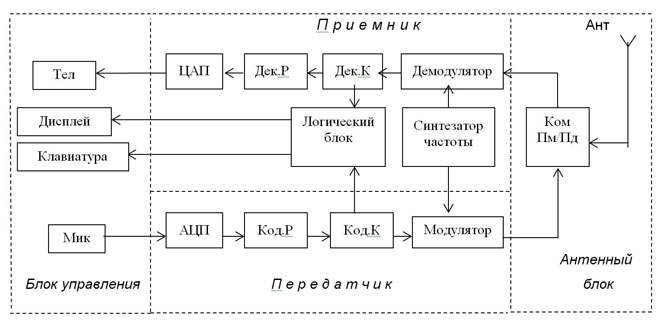
Functional Diagram
It does not show the design in detail, but contains a picture of the main blocks of the device with captions and functional units. With the help of this drawing, you can only learn about how the entire device system works and how the various elements are connected to each other. A functional diagram is appropriate for describing, for example, a complex electronic device, but not always for power supply devices.
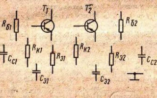
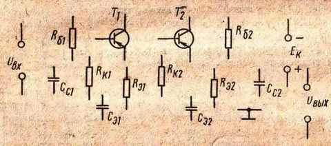
Schematic diagram
Contains a specific set of designations of elements, according to the composition of the device. In order to decipher the drawing correctly, it is necessary to know the basic graphic representation of electrical elements. In this kind of schemes, the connections between devices and their constituent elements themselves are indicated. To display power lines it is advisable to draw a line diagram, and to indicate the types of electrical circuits and control, control devices - a complete circuit diagram.
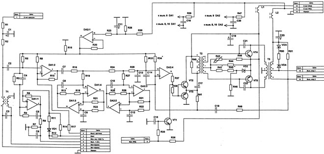
It should be noted that the single-line drawings show only the power part of the design, while the full schematic drawings show all elements of the circuit.
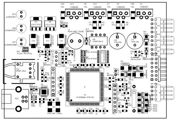
Wiring diagram
A circuit diagram is used when fitting components to circuit boards, assembling devices and electrical circuits. With its help the master determines which component should be placed where, at what distance from each other and in what order, according to the alphanumeric abbreviation next to the element, the deciphering of which is either a separate document, or is located in a table in the lower right corner above the main inscription. In addition to this, the arrangement of ratings is allowed.
Detailed information on each circuit type can be found in GOST 2.702-2011.
Basic graphic symbols
Let's move on to consideration of the elements themselves, made in accordance with interstate standards. By memorizing the most basic and most common ones, understanding many of the patterns will become much easier.
Basic Images
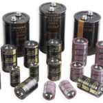
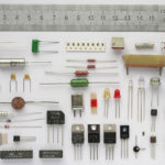
No electronic device is without having resistors, coils, capacitors, transistors, diodes, contacts, and switches. And some models of elements such as coils and capacitors have very small dimensions, depending on their rating, so beginners should not be surprised by their widespread use, and learn and remember how they are depicted in the drawings.
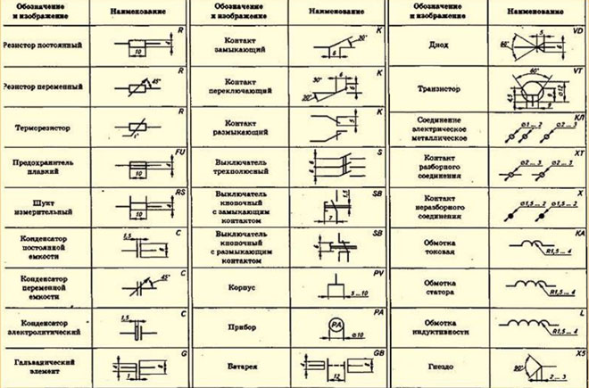
So, for example, according to GOSTs:
- The resistor is denoted by a rectangle, size 4X10mm;
- Condenser - Two parallel segments, the distance between them 1.5 mm;
- Coils - by arc lines, 2 to 4, depending on the purpose;
- Diodes - by triangles, to the top of which a line parallel to the base is drawn. The "arrow" formed by the graphic indicates in which direction the diode is open and in which direction it is closed;
- Transistors - A circle, 12mm in diameter, from which three lines or, in other words, contacts emerge. The arrow inside indicates that this pin of the transistor is the emitter and what type the element belongs to (n-p-n or p-n-p);
- Instruments such as an ammeter, wattmeter or voltmeter are indicated by the same circle, but with a diameter of 10mm and the conventional letter abbreviation PA, PW and PV respectively;
- The contacts are an open line, with a 6mm long section at an angle of 30° at one end.
Wiring and conductor lines
Conductors in all diagrams are mainly depicted by straight lines connecting the elements in the right sequence. It is allowed to put data above the line, to clarify the parameters of the applied voltage and current to the device as a whole or to a separate part of it. In such cases it is allowed to indicate:
- Type of current (direct, alternating, pulsed);
- Voltage value;
- Material;
- Wiring methods.
- Marks, etc.
Also on the conductor line itself, it is acceptable to mark with notches the total number of wires, e.g. in cable. The dots at the intersections of two or more conductors indicate their connection to each other, if not, then wires If not, then the wires will not interact with each other in any way and will simply cross each other.

Grounding in diagrams
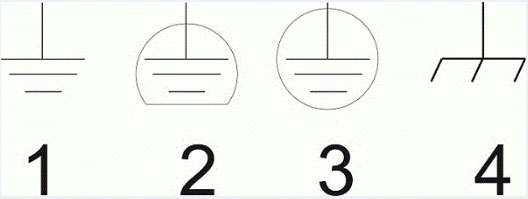
ESKD standards and GOST 2.721-74 also stipulate symbolism and grounding sign on the schemes. The system allows for three different options and connection of leads to the body of the device:
- The most common designation looks like a line with three perpendiculars drawn to it, located at a short distance from each other and having different sizes depending on the remoteness of the conductor (the farther away, the smaller). In the old drawings there is only such a sign of "ground".
- The second version shows a silent ground. The mark itself is exactly the same as the first one, with one exception: it is not drawn in a complete circle around it. This means that the unit as a whole or a component requires a separate groundingThe ground connection of the appliance or component requires a separate grounding conductor, isolated from the common "ground" line. This image is rare, but may well be found in drawings.
- Protective grounding is similar to a hybrid of the previous two signs, only the circle is shown not partially, as on the silent one, but completely covers the image. It is most common on power electrical drawings. In accordance with and safety requirements, the meaning of the image is such that it reflects the connections of live parts of the electrical circuit that are not energized, with grounding.
- The fourth option does not represent "ground" exactly, but rather the connection of the live parts of the device to its housing. However, even if the chassis is grounded, this type of connection cannot be called "ground", but it can occur frequently.
How the various currents are marked
Among other things, of particular importance in drawings is the correct indication of currents, for which the following signs have been introduced (indicated next to or inside the power source)
- Constant - straight short line
- AC - wavy line
- Pulsed - dotted line
A current value may be ascribed next to the symbol.
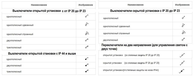
Wall sockets, switches and switches
Among all the accepted designations, the graphic representation of switches is divided into a number of groups according to:
- degree of protection;
- Type of installation (open, concealed);
- Number of keys.
Important! There is no UGO for dimmers and push-button light control devices.
Switches for two or three directions became common. They save power, and you can control two or three points, respectively.
The sockets are also divided according to the degree of protection and number of poles. Accordingly, additional alphanumeric signatures have been adopted to indicate the number and purpose of the devices.


Marking of light sources
Graphical depiction of lighting fixtures is necessary when drawing up plans and wiring diagrams of power supply for private houses, apartments as well as special complex lighting installations and various types of light bulbs. Therefore, their symbols have been introduced for them as well, which greatly speeds up the time of drawing up documentation.

Knowledge of these signs will be useful in everyday life for those who are going to study or make plans for the power supply of their homes.
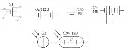
Power Supplies and Fuses
Among the sources, the following are widely used galvanic cells and batteries (G in the diagrams) are very common. It looks similar to the capacitor designation, with one difference - the segments are used of different lengths (short - "minus", long - "plus"). In cases where the supplied current or voltage from one source is insufficient, they are combined into a battery. This changes:
- the letter code from G to GB;
- Only the outermost cells are marked and the others are replaced by a dotted line;
- The outline of the battery is circled or oval, depending on its size.
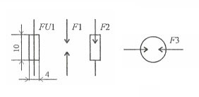
Also fuses (FU) are used in the devices, the designations of which are similar to resistors, but have an inner line denoting a metal filament burning inside. In addition, conventional (F2) or vacuum (F3) arresters are used in devices with high voltage power supply.
Knowing the symbols is useful for everyone who is planning to repair an electrical appliance or start installation work for their home, because thanks to a unified system there is no need to come up with your own graphic images. It is enough to remember the generally accepted ones.
Related articles: