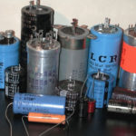
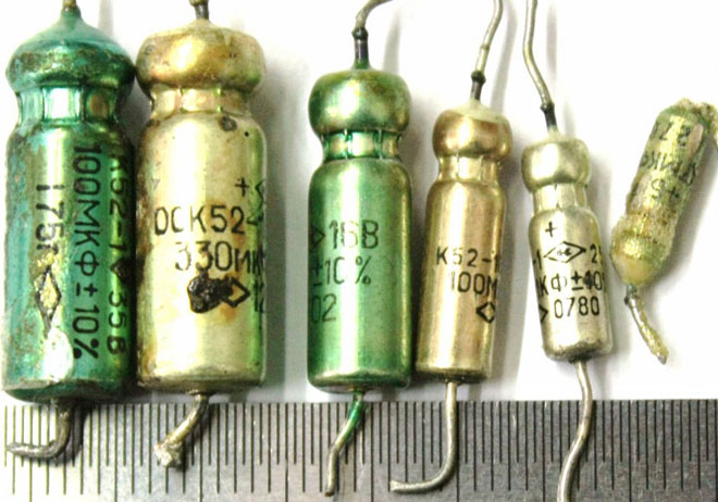
The basic information about the characteristics of capacitors, which are components of almost all electronic circuits, is usually placed on their bodies. Depending on the size of the element, the manufacturer, the time of production, the data printed on the electronic device is constantly changing not only in composition, but also in appearance.
As the case size decreased, the composition of alphanumeric designations changed, coded, replaced by color coding. The variety of internal standards used by the manufacturers of radioelectronic elements requires certain knowledge for the correct interpretation of the information on the electronic device.
Contents
Why do I need the marking?
The purpose of marking electronic components is to be able to identify them accurately. The marking of capacitors includes:
- data on the capacitor capacity - the main characteristic of the element;
- information on the nominal voltage at which the device maintains its performance;
- data on the temperature coefficient of capacitance, which characterizes the process of capacitor capacitance change in relation to changes in ambient temperature;
- The percentage of permissible deviation of the capacitance from the nominal value indicated on the housing;
- date of manufacture.
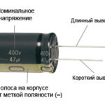
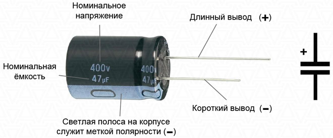
For capacitors that require observance of polarity when connected, it is mandatory to specify information that allows for correct orientation of the element in the electronic circuit.
The marking system for capacitors produced at the factories which were part of the USSR differed fundamentally from the marking system used by foreign companies at that time.
Marking of domestic capacitors
All post-Soviet enterprises are characterized by a fairly complete marking of radio elements, allowing for minor differences in designations.
Capacitance
The first and most important parameter of a capacitor is capacitance. Therefore, the value of this characteristic comes first and is coded with an alphanumeric designation. Since the unit of capacitance is the pharad, the alphabetic designation contains either the Cyrillic alphabet symbol "F" or the Latin alphabet symbol "F".
Since the farad is a large value, and the elements used in industry have much smaller ratings, the units have a variety of diminutive prefixes (miles, micro, nano and pico). The letters of the Greek alphabet are also used to denote them.
- One milli-farad is equal to 10-3 1 milli-farad is equal to 10 FM and is indicated as 1mF or 1mF.
- One microfarad is equal to 10-6 A microfarad is equal to 10 pharads and is referred to as 1μF or 1F.
- 1 nanofarad is equal to 10-9 1 nanofarad is equal to 10 nanofarads and is referred to as 1nF or 1nF.
- 1 picofarad is equal to 10-12 Farad and is designated 1pF or 1pF.
If the capacitance value is expressed as a fractional number, the letter denoting the dimension of the units is put in place of the comma. For example, 4n7 should read 4.7 nanofarads or 4700 picofarads, while n47 is equivalent to a capacity of 0.47 nanofarads or 470 picofarads.
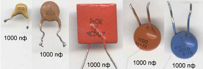
In case a capacitor is not marked with a rating, a whole value indicates that the capacitance is in picofarads, e.g. 1000, and a value expressed in decimals indicates the rating in microfarads, e.g. 0.01.
The capacitance of a capacitor indicated on the case rarely corresponds to the actual value and deviates from the nominal value within a certain range. The exact capacitance value sought in capacitor manufacturing depends on the materials used to manufacture the capacitors. The variation can range from thousandths of a percent to tens of a percent.
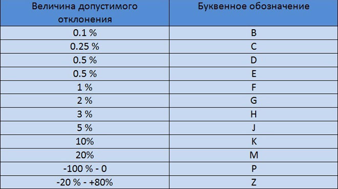
The value of the permissible deviation of capacitance is indicated on the capacitor body after the nominal value by putting a letter of the Latin or Russian alphabet. For example, the Latin letter J (Russian letter I in the old designation) indicates a deviation range of 5% in one direction or another, and the letter M (Russian letter V) - 20%.
A parameter such as the temperature coefficient of capacitance is included in the marking quite rarely and is applied mainly to small elements used in electrical circuits of time-retaining circuits. For identification, either an alphanumeric or color coding system is used.
There is also a combined alphanumeric and color marking. Its variants are so diverse that to determine the value of this parameter for each specific type of capacitor without errors it is necessary to refer to GOSTs or reference books on relevant radio components.
Rated Voltage
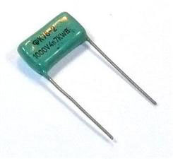
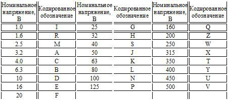
The voltage at which a capacitor will operate during its specified service life while maintaining its characteristics is called the rated voltage. For adequately sized capacitors, this is printed directly on the cell body where the numbers indicate the voltage rating and the letters indicate in what units it is expressed.
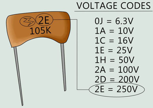
For example, 160V or 160V indicates that the rated voltage is 160 volts. Higher voltages are indicated in kilovolts, kV. On small capacitors, the voltage rating is coded with one of the letters of the Latin alphabet. For example, the letter I corresponds to a nominal voltage of 1 volt, and the letter Q corresponds to 160 volts.
Date of Issue
According to "GOST 30668-2000 "Electronic products. Marking" there are letters and numbers indicating year and month of issue.
"4.2.4 When marking year and month firstly indicate year of manufacture (two last digits of the year), then month - by two digits. If the month is designated by one digit, it is preceded by zero. For example: 9509 (1995, September).
4.2.5 For the articles, the overall dimensions of which do not make it possible to mark the year and the month of manufacture in accordance with 4.2.4, the codes given in Tables 1 and 2 should be used. The marking codes given in Table 1 shall be repeated every 20 years."
The date on which a particular manufacture was carried out may be shown not only as numbers but also as letters. Each year is correlated with a letter from the Latin alphabet. The months from January to September are denoted by numbers from one to nine. The month of October has a correlation with the number zero. November corresponds to the letter of the Latin type N, and December to the letter D.
| Year | Code |
|---|---|
| 1990 | A |
| 1991 | B |
| 1992 | C |
| 1993 | D |
| 1994 | E |
| 1995 | F |
| 1996 | H |
| 1997 | I |
| 1998 | K |
| 1999 | L |
| 2000 | M |
| 2001 | N |
| 2002 | P |
| 2003 | R |
| 2004 | S |
| 2005 | T |
| 2006 | U |
| 2007 | V |
| 2008 | W |
| 2009 | X |
| 2010 | A |
| 2011 | B |
| 2012 | C |
| 2013 | D |
| 2014 | E |
| 2015 | F |
| 2016 | H |
| 2017 | I |
| 2018 | K |
| 2019 | L |
Placement of markings on the enclosure
The marking plays an important role on all products. Often it is placed on the first line on the housing and has a capacity value. The same line will have the so-called tolerance value on it. If this line does not contain both markings, this can be done on the next line.
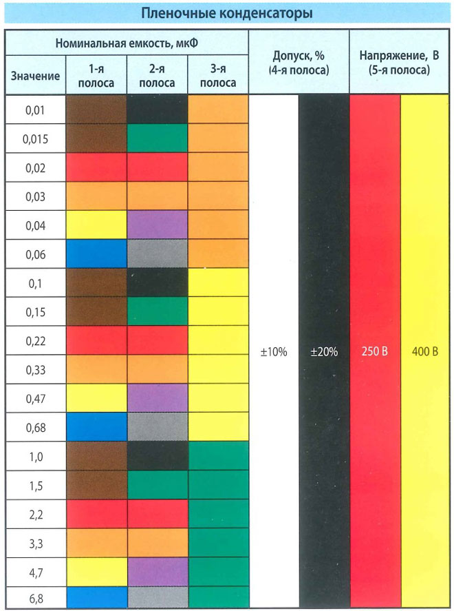
According to a similar system, the application of film-type condensates is carried out. The location of the elements must be placed according to a certain regulation, which is produced by GOST or TU for the element of the individual type.
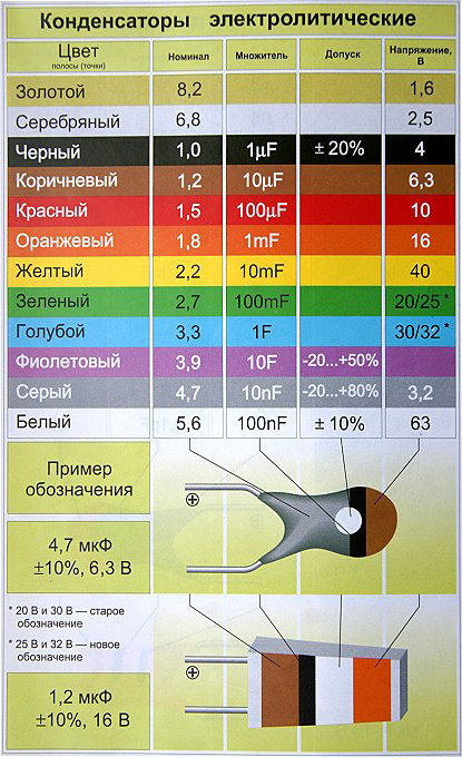
Color coding of domestic radio elements
In the production of lines with the so-called automatic types of installation appeared and color application, and its direct importance in the whole system.
Today, the most commonly used application is with four colors. In this case, the use of four stripes has been resorted to. So, the first bar together with the second one represent the capacity value in so-called picofarads. The third bar represents the deviation that can be allowed. And the fourth bar, in turn, represents the voltage of the nominal type.
Here is an example for you of how this or that element is marked - capacitance - 23*106 picofarads (24 F), allowable deviation from nominal - ±5%, nominal voltage - 57 V.
Import capacitor marking
Nowadays standards, which were adopted from IEC, apply not only to foreign types of equipment, but also to domestic ones. This system involves applying a code-type marking to the body of the product, which consists of three direct digits.
The two digits, which are located at the beginning, denote the capacity of the item and in units such as picofarads. The digit that is placed third in order is the number of zeros. Consider this with the example of 555, which is 5500000 picofarads. In the event that the capacity of the product is less than one picofarad, the number zero is indicated from the beginning.
There is also a three-digit type of coding. This type of application applies only to parts that are high-precision.
Color coding of imported capacitors
The designation of names on such an object as a capacitor has the same production principle as on resistors. The first bars on the two rows denote the capacity of this device in the same measuring units. The third stripe has a designation about the number of direct zeros. But there is no blue coloring at all, blue is used instead.
It is important to know that if the colors are the same in a row, then it is advisable to implement gaps between them, so that it was clearly understood. After all, in another case, these stripes will merge into one.
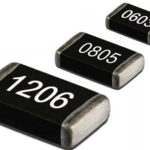
Marking smd components
The so-called SMD components are used for surface mounting and thus have extremely small dimensions. Accordingly, for this reason, they are marked with markings that have minimal dimensions. Because of this there is a system of abbreviation of both numbers and letters. The letter represents the capacity of a particular object in units of picofarads. As for the number, it stands for the so-called multiplier to the tenth power.
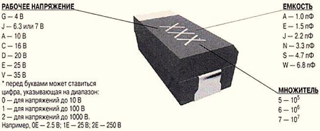
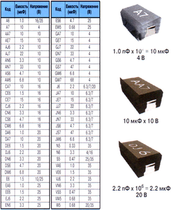
Very common electrolytic capacitors may have a basic parameter type value on their direct housing. This value has a fraction as a decimal type.
Conclusion .
As you have already guessed, the labeling of these items has a very wide variation. Especially a large number of markings have capacitors that were produced abroad. Quite often there are products not of large size, the parameters of which can be determined by special measurements.
Related articles: