Resistors are among the most widely used elements in electronics. This name left the narrow confines of the terminology of radio amateurs long ago. And for anyone with even a slight interest in electronics, the term should not cause confusion.
Contents
What is a resistor
The simplest definition is as follows: a resistor is an element in an electrical circuit that provides resistance to the current flowing through it. The name of the element comes from the Latin word "resisto" - "resist", radio amateurs often call this part so - resistance.
Let's look at what resistors are, what resistors are needed for. Answering these questions involves familiarity with the physical meaning of the basic concepts of electrical engineering.
To explain how a resistor works, you can use the analogy of water pipes. If we somehow obstruct the flow of water in the pipe (for example, by reducing its diameter), there will be an increase in internal pressure. By removing the obstruction, we reduce the pressure. In electrical engineering, this pressure corresponds to voltage - by making it harder for an electric current to flow, we increase the voltage in the circuit; by decreasing the resistance, we decrease the voltage as well.
By changing the diameter of the pipe, we can change the speed of water flow, in electrical circuits, by changing the resistance, we can regulate the strength of the current. The value of resistance is inversely proportional to the conductivity of the element.
The properties of resistive elements can be used for the following purposes:
- Conversion of current into voltage and vice versa;
- limiting the flowing current to obtain a given value of current;
- Creation of voltage dividers (for example, in measuring instruments);
- other special purposes (e.g., reducing radio interference).
Explain what a resistor is and what it is used for with the following example. The familiar LED glows at low currents, but its own resistance is so small that if the LED is placed in a circuit directly, even at 5 V, the current flowing through it will exceed the allowable parameters of the part. From such a load the LED will fail at once. Therefore, the circuit includes a resistor, the purpose of which in this case is to limit the current to a given value.
All resistive elements are passive components of electrical circuits, unlike active ones, they do not give energy to the system, but only consume it.
Having understood what resistors are, it is necessary to consider their types, designation and marking.
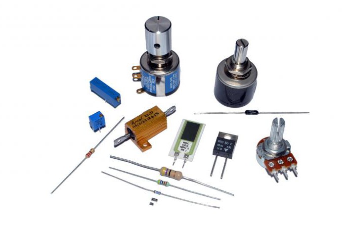
Types of Resistors
Types of resistors can be broken down into the following categories:
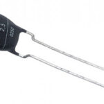
- Non-adjustable (constant) - wirewound, composite, film, carbon, etc.
- Adjustable (variable and trim). Adjustable resistors are used to adjust electrical circuits. Variable resistance elements (potentiometers) are used to adjust signal levels.
A separate group is represented by semiconductor resistive elements (thermoresistors, photoresistors, varistors, etc.).
The characteristics of resistors are determined by their purpose and are set during manufacturing. Among the key parameters are:
- Nominal resistance. This is the main characteristic of the element and is measured in ohms (Ohm, kOhm, Mohm).
- Allowable deviation as a percentage of the specified nominal resistance. Means a possible variation of the index, determined by the technology of manufacture.
- Power dissipation - the maximum power a resistor can dissipate under long-term load.
- Temperature coefficient of resistance - a value that shows the relative change in resistance of the resistor when the temperature changes by 1 ° C.
- Operating voltage limit (electrical strength). It is the maximum voltage at which the part retains its stated parameters.
- Noise characteristic - the degree of distortion introduced into the signal by the resistor.
- Moisture and temperature resistance - the maximum values of humidity and temperature, exceeding which may lead to failure of the part.
- Voltage Factor. A value that takes into account the dependence of resistance on the applied voltage.
The use of resistors in the field of ultrahigh frequencies gives importance to additional characteristics: parasitic capacitance and inductance.
Semiconductor Resistors
They are semiconductor devices with two leads that have a dependence of electrical resistance on the parameters of the environment - temperature, light, voltage, etc. Semiconductor materials doped with impurities, the type of which determines the dependence of conductivity on external influences, are used to manufacture such parts.
There are the following types of semiconductor resistive elements:
- Linear resistor. Made of low-alloy material, this element has a low dependence of resistance on external action in a wide range of voltages and currents, it is most often used in the production of integrated circuits.
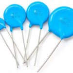
- Varistor - element, the resistance of which depends on the strength of the electric field. This property of varistor defines its scope of application: to stabilize and regulate electrical parameters of devices, to protect against overvoltage, for other purposes.
- Thermistor. This type of non-linear resistive elements has the ability to change its resistance depending on the temperature. There are two types of thermistors: a thermistor whose resistance decreases with increasing temperature, and a posistor whose resistance increases with temperature. Thermistors are used where constant control of the temperature process is important.
- Photoresistor. The resistance of this device changes when exposed to light and is independent of the applied voltage. Lead and cadmium are used in manufacture, and in some countries this has led to these parts being phased out for environmental reasons. Today, photoresistors are inferior to photodiodes and phototransistors, which are used in similar assemblies.
- Tensor Resistor. This element is designed to change its resistance depending on the external mechanical impact (deformation). It is used in nodes that convert mechanical action into electrical signals.
Semiconductor elements such as linear resistors and varistors are characterized by a weak degree of dependence on external factors. For strain gauges, thermoresistors and photoresistors, the dependence of the characteristics on influence is strong.
Semiconductor resistors are intuitively labeled in the schematic.
Resistor in a circuit
In Russian schemes, elements with constant resistance are usually designated as a white rectangle, sometimes with the letter R above it. In foreign schemes you can find a resistor in the form of a zigzag symbol with a similar letter R on top. If any parameter of the part is important for the operation of the device, it is customary to indicate it on the schematic.
The power can be indicated by the bars on the rectangle:
- 2W - 2 vertical dashes;
- 1 W - 1 vertical line;
- 0.5 W - 1 line;
- 0.25 W - one oblique line;
- 0.125 W - two oblique lines.
It is acceptable to indicate the power on the diagram in Roman numerals.
The designation of variable resistors is distinguished by the presence of an additional line above the rectangle with an arrow, symbolizing the possibility of adjustment, numbers can be indicated by pin numbering.
Semiconductor resistors are marked with the same white rectangle, but crossed by a slash line (except for photoresistors) with a letter indicating the type of control action (U - for a varistor, P - for a strain gauge resistor, t - for a thermistor). The photoresistor is denoted by a rectangle in a circle, to which two arrows, symbolizing light, are directed.
The parameters of the resistor do not depend on the frequency of the flowing current, which means that this element functions equally in DC and AC circuits (both low and high frequency). Exceptions are wire-wound resistors, which are inductive and can lose energy due to radiation at high and ultrahigh frequencies.
Depending on the requirements for the properties of the electrical circuit, resistors can be connected in parallel and in series. The formulas for calculating the total resistance for the different circuit connections differ considerably. In a series connection, the total resistance is equal to the simple sum of the values of the elements in the circuit: R = R1 + R2 +... + Rn.
In parallel connection, to calculate the total resistance, add the values inverse to the values of the elements. This will result in a value which is also the inverse of the total value: 1/R = 1/R1 + 1/R2 + ... 1/Rn.
The total resistance of the resistors connected in parallel will be lower than the lowest one.
Ratings
There are standard resistance values for resistive elements, called "resistor rating series". The approach to creating this row is based on the following consideration: the step between the values should overlap the allowable deviation value (error). Example - if the rating of an element is 100 Ohm and the tolerance is 10%, then the next value in the series will be 120 Ohm. This step avoids unnecessary values, because the neighboring ratings together with the error variation practically cover the whole range of values between them.
Resistors produced are grouped into series that differ in tolerances. Each series has its own nominal range.
The differences between the series are:
- E 6 - 20% tolerance;
- E 12 - 10% tolerance;
- E 24 - tolerance of 5% (sometimes 2%);
- E 48 - tolerance of 2%;
- E 96 - tolerance 1%;
- E 192 - 0.5% tolerance (can be 0.25%, 0.1% and lower).
The most common E 24 series includes 24 resistance ratings.
Labeling
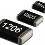
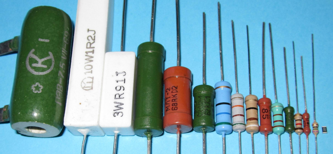
The size of a resistive element is directly related to its power dissipation, the higher it is, the larger the size of the part. While it is easy to indicate any numerical value on schematics, the marking of products can be difficult. The miniaturization trend in electronics production makes it necessary to use smaller and smaller elements, which makes it more difficult both to put the information on the enclosure and to read it.
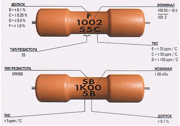
To facilitate the identification of resistors in the Russian industry, alphanumeric marking is used. The resistance is marked as follows: the nominal value is indicated by digits, and the letter is put either behind the digits (in case of decimal values), or before them (for hundreds). If the rating is less than 999 ohms, the number is written without a letter (or there may be letters R or E). If the value is specified in kOhm, the letter K is put after the number, and the letter M corresponds to the value in Mohm.
U.S. resistors are marked with three digits. The first two suggest the denomination, the third the number of zeros (tens) added to the value.
In robotic production of electronic assemblies, the applied symbols are often on the side of the part that faces the board, which makes it impossible to read the information.
Color coding
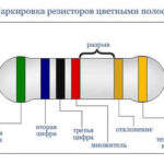
To keep information about a part's parameters readable from either side, color coding is used - the paint is applied in circular stripes. Each color has its own numerical value. The stripes on the parts are placed closer to one of the pins and are read from left to right. If it is not possible to move the color markings to one terminal due to the small size of the part, the first stripe is made twice as wide as the other strips.
Items with an allowable error of 20% are marked with three lines, for an error of 5-10% 4 lines are used. The most accurate resistors are marked with 5-6 lines, the first 2 of them correspond to the part rating. If the bands are 4, the third one indicates the decimal multiplier for the first two bands, the fourth line means the accuracy. If the bars are 5, then the third one indicates the third digit of the nominal, the fourth one indicates the decimal multiplier (number of zeros), and the fifth one indicates the accuracy. The sixth line means the temperature coefficient of resistance (TCR).
In the case of the four-band marking, the gold or silver stripe always comes last.
All the designations look complicated, but the ability to quickly read the markings comes with experience.
Related articles: