All electrical network projects are created on the basis of special technical documentation where calculated and operating capacities, parameters and characteristics of a room or building electrical network project are shown. All of this documentation is regulated by "Rules of technical operation of electrical installations of consumers".. The rules were developed on the basis of current legislation, state standards and other normative and technical documents. The rules of technical operation take into account the proposals of electrical repair organizations and research institutes. The fundamental document in the design documents is the scheme of power supply.

Contents .
Single-line diagram of power supply: what it is and why it is needed
Electric circuit diagram
A complete picture of how an electrical product or object functions is given by the circuit diagram. It includes the entire list of elements that make up the object. The circuit diagram is the basis for all subsequent documents and drawings required for the construction of the facility or equipment. The circuit diagram shows the drawings that show the complete electromagnetic and electrical connections of the elements, as well as the characteristics of all components of the object. Drawing a schematic diagram is made in two ways: Combined and spaced out..
By the distributed method use circuits that contain many contactors, relays and various contacts. To create such circuits the elements are assigned values sequentially. But the individual circuits are placed in parallel. All the parts that make up the elements and devices or individual elements in the scheme are drawn separately from each other, so that the scheme looks more clearly.
With the combined method all parts of the elements or devices are drawn in the schematic representation of the power supply system in close proximity to one another.
In the free fields of diagrams that are made by the spaced method, it is acceptable to place graphical symbols of devices made by the combined method.
If the object contains such elements that are used partially, then these elements must be shown in full on the diagram, and it should be indicated which parts are used in full and which are not. Those that are fully used should be depicted longer in the diagram, and the parts of unused elements should be depicted shorter.
What is meant by a single-line diagram
Single-line diagram differs from the schematic diagram in the fact that on the single-line diagram all electrical connections of the object are made in a simplified form and marked with one line regardless of the number of phases. This way of simplification is used not only to show the power lines, but also to indicate different types of cables, the number of wires in which can be more than three.
Types of one-line diagrams: design and actuation diagrams
Calculation scheme Use it during the design and selection phase of electrical equipment. It serves as the basis for the other diagrams required for the construction of the facility and its commissioning. All necessary parameters which will provide full fire safety of the object are taken into account when drawing up the design diagram.
On the ready object flow diagram is used when the electrical networks are to be modernized. In this case, the drawing is developed on the basis of the existing installations. Before making a single-line diagram of the power supply, a comprehensive inspection of the facility is mandatory. The modernized scheme is developed taking into account the correction of all defects that were identified during the works.
Main points for designing a single-line diagram of power supply
What a one-line diagram of power supply should include
In order to commission the facility, the following sequence of actions is necessary:
- make a request for technical specifications to the power grid organization;
- Drawing a single-line diagram;
- Approve the finished scheme in the organization that issued the specifications.
Stages of approval of the executive scheme are exactly the sameas for the design scheme.
To easily pass all stages of the preparation of the one-line diagram, it must contain information of the following nature:
- the main and reserve point of connection to the power grid;
- type of input and output switchgear;
- electricity metering devices;
- ways of laying wires and cablestype and length of wires and cables;
- circuit breakers and their technical parameters;
- load on the power grid with indication of power and current;
- lighting circuits.
Design rules, GOST requirements.
When designing single-line diagrams must comply with the requirements of GOST ESKD (Unified System for Design Documentation), which strictly prescribed algorithm for creating electric circuits:
- GOST 2.702-2011 - Provisions for the development of electrical circuits;
- GOST 2.709-89 - wires, contact connections and circuit sections;
- GOST 2.755-87 - switching devices and contact connections;
- GOST 2.721-74 - general use designations;
- GOST 2.710-81 - alphanumeric signs.
All electrical elements and power circuits are marked with a thicker line on the schemes.
All electrical circuits must be labeled. All circuits should be labeled from source to consumer in sequence. Circuits are labeled with Arabic numerals and capital Latin letters. The numbers indicate the circuit sequence, and the letters — The numbers indicate the sequence of circuits, and the letters the phases of alternating current.
Sections of a circuit with separated contacts (relay windings, resistors etc.), must be marked according to polarity. Positive polarity of circuit sections are marked with odd numbers, polarity with negative values — with even numbers.
Circuit sections that pass through different contact connections must have the same markings. Markings on the diagram are described on the left or above the circuit picture.
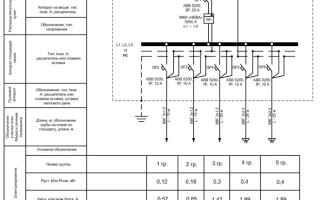
The diagram should show the full characteristics of the input and output circuits. Characteristics refer to voltage, resistance, frequency, inductance, current, etc.
All parameters of electrical circuits, connection addresses can be written in tables to simplify the reading of the schematic. Tabular variant replaces the schematic designations of input and output elements. When constructing a diagram, the table looks more clearly, it is performed in any form, since it is not regulated by GOST.

If a table is placed in place of an element, it is attributed a positional designation of the element, instead of symbols for drawings.
When performing a single-line diagram in the free field of the scheme it is acceptable to place technical specifications in the form of text:
- brands, cross-sections and colors of cables and wirescross-sections, colors of the cables and wires connecting the elements of the product;
- installation requirements;
- designation of individual circuits.
If the diagram is made on several sheets, then certain requirements must be taken into account:
- The design of a common list of all elements;
- Within the product, all position designations of elements should be numbered consecutively.
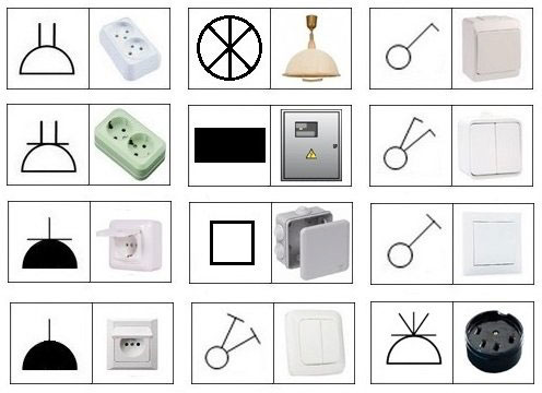
Symbols used when drawing up one-line diagrams
All power supply elements are strictly defined by regulatory documents and State Standards. Each element has its own SymbolsThey are reflected in the drawings.
- The rectangles . are used to denote all panels;
- rectangles with a line underneath — are the panel elements of the trunkings;
- The black rectangles — are group boxes;
- Rectangles with two diagonals — are emergency connection panels;
- squares with a line underneath are one-way service panels and distribution cabinets;
- squares with a line on the bottom and top the square at the bottom to denote enclosures and panels for two-way service;
- A square with a thickened vertical line indicates a pullout box;
- a circle with a thickened cross line and a line from the center of the circle downward — is a junction box;
- The circle from which a line extends upward diagonally to the right — is switchIf there are several poles, there will be as many lines as there are poles;
- the circle from which down the diagonal to the right the line — is an open set, if there are several elements, there will be as many lines as there are elements;
- a circle from which a diagonally right-crossed line goes down the diagonal is a hidden setting. — is a hidden setting. If there are several elements, there will be as many crossed out lines as there are elements;
- black circle — a switch with a high degree of protection;
- a circle with opposite diagonals up and to the right and down and to the left — is a switch with different directions
- a semicircle with a flat side down and a line coming up from the top of the semicircle indicates a socket outlet;
- a semicircle with two lines upward — a receptacle with two poles
- a semicircle with one or two lines up and an additional horizontal — receptacle with protective contact
- semicircle with a line from the center to the top — Flush-mounted socket outlet;
- black half-circle — socket outlet with strong protection.

Lighting designations:
- circles — light fixtures;
- a circle divided into 6 parts — chandelier;
- long rectangle — luminaires with fluorescent lamps;
- a circle in the center with a cross dotted line and a bold line — tether;
- a circle with the letter T inverted on its left side — exterior lighting fixtures;
- a blacked-out triangle with a V-shaped fork at the top — a bulbous wall socket;
- diagonally crossed circle — pendant chuck
- a circle diagonally crossed only on the outer side of the circle - ceiling chuck;
- circle with the letter A — ammeter
- circle with the letter V — voltmeter
- circle with an arrow up inside the circle - galvanometer;
- a square with the letter t inside and an arrow to the right — temperature gauge;
- a square with the letter N and a lightning bolt — oscilloscope;
- a tall rectangle with the top segment separated and the letters Wh — electric meter.
Special programs for drawing single-line diagrams of power supply
To properly draw technical documentation, you need to study the requirements of GOSTs, but you can use specially designed computer programs. When using specialized programs, all requirements will be taken into account automatically.
- "1-2-3 scheme" — A very easy to understand free program. Suitable for students and beginners;
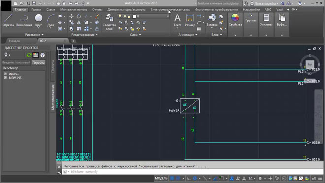
- "AutoCAD Electrical" — a very popular program among experienced specialists, understandable and giving advanced possibilities for the development of electrical circuits;
- "Microsoft Visio" — a free program for laymen who use the program to draw up electrical schematics for the construction of a private home;
- XL Pro² — the free program for designing low-voltage switchgear (NKU);
- "Compass-Electric" — free program for engineers and specialists of energy complexes;
- Rapsodie — another program for designing low-voltage complete devices. The program allows you to easily assemble the necessary switchgear cabinet according to the given parameters;
- "Eagle" — program is available in free and paid version, in a paid package is available more extended by technical parameters version;
- "DipTrace" — software for the creation of electrical circuits, PCB drawings to create electronic products.
In order to competently and clearly develop a single-line diagram it is necessary to strictly follow GOSTs and standards, know how to use modern software products and have an understanding of electrical installations, but it is best to use the services of a specialist.
Related articles: