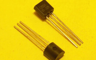
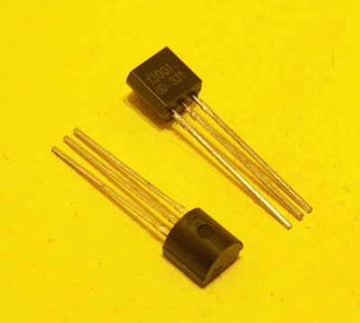
Transistor 13001 (MJE13001) is a silicon triode manufactured using planar epitaxial technology. It has N-P-N structure. It refers to medium-power devices. Produced for the most part in factories located in Southeast Asia, and used in electronic devices manufactured in the same region.
Contents
Main Technical Characteristics
The main features of transistor 13001 are:
- high operating voltage (base-collector - 700 volts, collector-emitter - 400 volts, according to some sources - up to 480 volts);
- Short switching times (current rise time tr=0.7 microseconds, the decay time tf=0.6 μs, both measured at a collector current of 0.1 mA);
- High operating temperature (up to +150 °C);
- high power dissipation (up to 1 W);
- Low collector-emitter saturation voltage.
The last parameter is declared at two modes:
| Collector current, mA | Base current, mA | Collector-emitter saturation voltage, V |
|---|---|---|
| 50 | 10 | 0,5 |
| 120 | 40 | 1 |
Also as an advantage, manufacturers claim the low content of the transistor of hazardous substances (RoHS compliance).
Important! In datasheets of different manufacturers of 13001 series transistors the characteristics of the semiconductor device differ, therefore some discrepancies (usually within 20%) are possible.
Other parameters that are significant for operation:
- The maximum continuous base current is 100 mA;
- maximum pulse base current - 200 mA;
- 180 mA collector current limit;
- maximum collector pulse current - 360 mA;
- maximum base-emitter voltage - 9 volts;
- storage time - from 0.9 to 1.8 μs (at 0.1 mA collector current);
- Base-emitter saturation voltage (at 100 mA base current, 200 mA collector current) - no more than 1.2 volts;
- maximum operating frequency - 5 MHz.
Static current transfer coefficient for different modes is stated in the range:
| Collector-emitter voltage, V | Collector current, mA | Gain | |
|---|---|---|---|
| Smallest | Highest | ||
| 5 | 1 | 7 | |
| 5 | 250 | 5 | |
| 20 | 20 | 10 | 40 |
All specifications are declared at an ambient temperature of +25 °C. The transistor can be stored at ambient temperatures ranging from minus 60 to +150 °C.
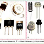
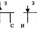
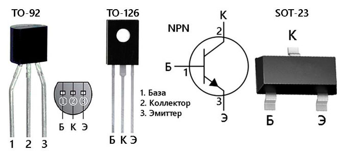
Enclosures and Keying
The 13001 transistor is available in flexible lead-in plastic packages for true hole mounting technology:
- TO-92;
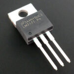
- TO-126.
SMD packages are also available:
- SOT-89;
- SOT-23.
Transistors in SMD packages are marked with letters H01A, H01C.
Important! Transistors from different manufacturers may be prefixed with MJE31001, TS31001 or have no prefix. Due to lack of space on the package the prefix is often not specified and such devices may have different pinout. If there is a transistor of unknown origin, it is better to clarify the pin positions with a multimeter or a device for checking transistors.
Domestic and foreign equivalents
Direct analog transistor 13001 There is no direct analog in Russian silicon triodes nomenclature, but for medium operational modes, you can use silicon semiconductor devices of N-P-N structure from the table.
| Transistor Type | Highest power dissipation, W | Collector-base voltage, volts | Base - Emitter voltage, volts | Edge frequency, MHz | Highest collector current, mA | h FE |
|---|---|---|---|---|---|---|
| KT538A | 0,8 | 600 | 400 | 4 | 500 | 5 |
| KT506A | 0,7 | 800 | 800 | 17 | 2000 | 30 |
| KT506B | 0,8 | 600 | 600 | 17 | 2000 | 30 |
| КТ8270A | 0,7 | 600 | 400 | 4 | 500 | 10 |
For modes close to the maximum, it is necessary to choose analogs carefully so that the parameters allow to operate the transistor in a particular circuit. It is also necessary to clarify the pin-out of the devices - it may not coincide with the pin-out of 13001, it can lead to problems with the installation on the board (especially for SMD version).
As for foreign analogs, the same high-voltage but more powerful silicon N-P-N transistors are suitable for replacement:
- (MJE)13002;
- (MJE)13003;
- (MJE)13005;
- (MJE)13007;
- (MJE)13009.
They differ from the 13001 mostly in increased collector current and increased power that the semiconductor device can dissipate, but there may also be a difference in the housing and pin layout.
In each case, it is necessary to check the pinout. In many cases LB120 transistors, SI622 etc. can do the trick, but you have to carefully compare the specific characteristics.
For example, the LB120 has the same collector-emitter voltage of 400 volts, but you cannot supply more than 6 volts between the base and the emitter. It also has a slightly lower maximum power dissipation of 0.8 W compared to the 13001's 1 W. This has to be taken into account when deciding to replace one semiconductor device with another. The same applies to the higher power, higher voltage domestic silicon transistors of the N-P-N structure:
| Domestic Transistor Type | Highest collector-emitter voltage, V | Maximum collector current, mA | h21э | Case |
|---|---|---|---|---|
| KT8121A | 400 | 4000 | <60 | KT28 |
| KT8126A | 400 | 8000 | >8 | KT28 |
| KT8137A | 400 | 1500 | 8..40 | KT27 |
| KT8170A | 400 | 1500 | 8..40 | KT27 |
| KT8170A | 400 | 1500 | 8..40 | KT27 |
| KT8259A | 400 | 4000 | up to 60 | TO-220, TO-263 |
| KT8259A | 400 | 8000 | up to 60 | TO-220, TO-263 |
| KT8260A | 400 | 12000 | up to 60 | TO-220, TO-263 |
| KT8270 | 400 | 5000 | <90 | KT27 |
They replace 13001 series devices functionally, have more power (and sometimes higher operating voltages), but the pin assignment and housing dimensions may be different.
Applications for 13001 transistors
The 13001 series transistors are designed specifically for low power converter applications as key (switching) elements.
- mobile device mains adapters;
- Electronic ballasts for low-power fluorescent lamps;
- electronic transformers;
- Other pulse devices.
There are no principal restrictions on the use of 13001 transistors as transistor keys. It is also possible to use these semiconductors in low-frequency amplifiers in cases where special amplification is not required (current transfer ratio of 13001 series is small by modern standards), but in these cases rather high parameters of these transistors in operating voltage and their high speed response are not realized.
In these cases, it is better to use more common and cheaper types of transistors. Also when building amplifiers we must remember that the complementary pair of the transistor 31001 is missing, so there can be problems with the organization of the push-pull cascade.
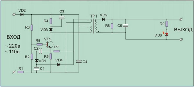
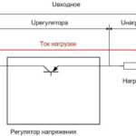
The figure shows a typical example of using the transistor 13001 in a battery charger for a portable battery. A silicon triode is included as a key element, which forms pulses on the primary winding of transformer TP1. It withstands the full rectified line voltage with a large margin and does not require additional circuitry measures.
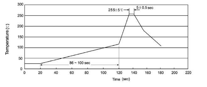
When soldering transistors, a certain amount of care must be taken to avoid unnecessary heat. The ideal temperature profile is shown in the figure and consists of three steps:
- The preheating stage lasts about 2 minutes, during which time the transistor is heated from 25 to 125 degrees;
- the actual soldering lasts about 5 seconds at a maximum temperature of 255 degrees;
- the final stage is de-icing at a rate of 2 to 10 degrees per second.
This schedule is difficult to follow at home or in the workshop, and it is not that important when disassembling and assembling a single transistor. The main thing is not to exceed the maximum allowable soldering temperature.
Transistors 13001 have a reputation for fairly reliable products, and under operating conditions not exceeding the established limits, can last a long time without failure.
Related articles: