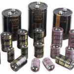
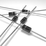
Many types of electric capacitors have no polarity and therefore their inclusion in a circuit is not difficult. Electrolytic charge accumulators constitute a special class because. have positive and negative outputs, so when you connect them you often face the problem of how to determine the polarity of the capacitor.
Contents
How do I determine the polarity of an electrolytic capacitor?
There are a number of ways to check the location of the plus and minus on a device. The polarity of a capacitor is determined as follows:
- by marking, i.e. by the inscriptions and drawings on its case;
- by appearance;
- with the help of a universal measuring instrument - multimeter.
It is important to correctly identify the positive and negative contacts, so that after installation, when voltage is applied, the circuit will not fail.
By marking
The labeling of charge accumulators, including electrolytic ones, depends on the country, the manufacturing company and the standards, which change over time. Therefore, the question of how to determine the polarity on a capacitor does not always have a simple answer.
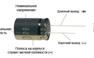
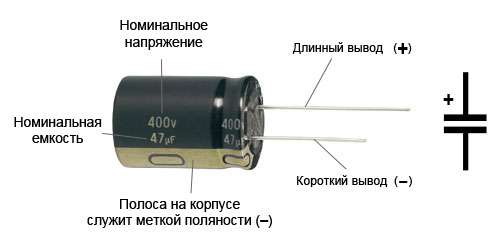
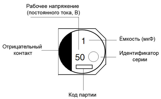
The designation of the plus of a capacitor
On domestic Soviet products were marked only the positive contact - the sign "+". This sign was put on the case next to the positive terminal. Sometimes in the literature the positive terminal of electrolytic capacitors is called an anode because they not only accumulate charge passively, but are also used to filter alternating current, i.e. have the properties of an active semiconductor device. In some cases the "+" sign is put on the printed circuit board, near to the positive pin of the storage device placed on it.
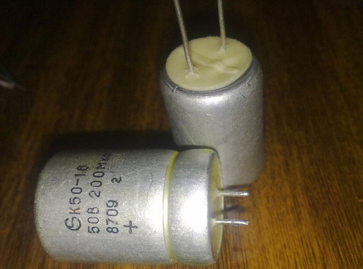
On products of K50-16 series the polarity marking is put on the bottom, made of plastic. Other models of the K50 series, such as K50-6, have the "plus" sign painted on the bottom of the aluminum housing, next to the positive terminal. Sometimes imported products made in the former socialist camp are also marked on the bottom. Modern domestic products meet worldwide standards.
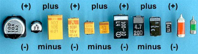
The labeling of SMD (Surface Mounted Device) capacitors designed for surface mounting (SMT - Surface Mount Technology) is different from the usual. Flat models have a black or brown body in the form of a small rectangular plate, with a silver band with a "plus" sign on the positive terminal.
Marking of minus
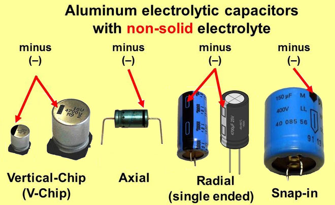
The principle of polarity marking of imported products differs from the traditional standards of the domestic industry and consists in the algorithm: "to know where the plus is, you must first find where the minus is". The location of the negative contact is shown both by special signs and by the color of the case.
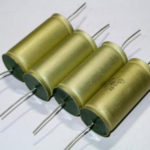
For example, a black cylindrical case has a light gray stripe across the height of the cylinder on the side of the negative lead, sometimes called the cathode. The strip is printed with a dashed line, or elongated ellipses, or a "minus" sign, and 1 or 2 angle brackets with a sharp angle pointing toward the cathode. The range with other ratings is distinguished by a blue case and a pale blue stripe on the negative contact side.
Other colors are also used for marking, following the general principle: dark body and light stripe. This marking is never completely obliterated and therefore it is always possible to identify the polarity of the "electrolyte", as electrolytic capacitors are called for brevity in radio engineering jargon.
The body of SMD capacitors made in the form of an aluminum metal cylinder remains unpainted and has a natural silver color, while the segment of the round upper end is painted intense black, red or blue and corresponds to the position of the negative terminal. Once the element is mounted on the PCB surface, the partially painted end of the enclosure, indicating polarity, is clearly visible in the schematic, as it has a greater height than flat elements.
On the surface of the board is applied corresponding marking polarity of cylindrical SMD device: it is a circle with a segment shaded with white lines, where the negative contact is located. However, note that some manufacturers prefer to mark the positive contact of the device in white.
By appearance
If the markings are erased or unclear, it is sometimes possible to determine the polarity of a capacitor by analyzing the appearance of the case. Many capacitors with terminals on one side and which have not been assembled have a longer plus side than the negative side. ETO products, now obsolete, have the appearance of 2 cylinders stacked on top of each other: larger diameter and small height, and smaller diameter but significantly taller. The contacts are centered on the ends of the cylinders. The positive lead is mounted in the end of the larger diameter cylinder.
Some high-power electrolytes have the cathode lead out to the body, which is connected by soldering to the circuit chassis. Accordingly, the positive terminal is isolated from the case and located on top of it.
The polarity of a wide class of foreign and now domestic electrolytic capacitors is determined by the light stripe associated with the negative pole of the device. If neither the marking nor the appearance of the electrolyte polarity cannot be determined, then and then the problem of "how to know the polarity of the capacitor" is solved by using a universal tester - multimeter.
Using a multimeter
Before conducting experiments it is important to assemble the circuit so that the test voltage of the direct current source (DCS) does not exceed 70-75% of the nominal value indicated on the storage case or in the reference book. For example, if the electrolyte is rated at 16 V, the power supply should deliver no more than 12 V. If the rating of the electrolyte is unknown, start the experiment with small values in the range of 5-6 V, and then gradually increase the voltage at the power supply output.
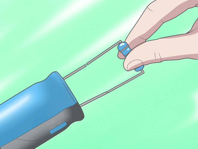
The capacitor must be completely discharged - to do this, connect its legs or leads short-circuited for a few seconds with a metal screwdriver or tweezers. You can connect an incandescent lamp from a pocket lamp to them until it goes out or a resistor. Then you should carefully inspect the product - it should not be damaged and bloated housing, especially the protective valve.
The following devices and components will be required:
- IP - battery, battery, computer power supply or a specialized device with adjustable output voltage;
- multimeter;
- resistor;
- assembly accessories: soldering iron with solder and rosin, side cutters, tweezers, screwdriver;
- a marker for marking the polarity signs on the body of the electrolyte being tested.
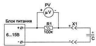
Then the electrical circuit should be assembled:
- parallel to the resistor by means of "crocodiles" (i.e. probes with clamps) connect a multimeter set to measure direct current;
- Connect the plus terminal of the power supply to the terminal of the resistor;
- connect the other terminal of the resistor to the terminal of the capacitor, and its second terminal connect to the minus terminal of the power supply.
If the polarity of the electrolyte connection is correct, the multimeter will not register the current. So, the contact connected to the resistor will be positive. Otherwise the multimeter will show current. In this case, the plus contact of the electrolyte has been connected to the minus terminal of the power supply.
Another way of checking is different in that the multimeter connected in parallel to the resistor is switched to DC voltage measurement mode. In this case, if the capacitance is connected correctly, the instrument will show a voltage, the value of which will then tend to zero. If connected incorrectly, the voltage will first drop, but then will be fixed at a non-zero value.
According to method 3, the device measuring the DC voltage is not connected in parallel to the resistance, but to the tested capacitance. If the poles of the capacitance are connected correctly, the voltage will reach the value set on the power supply. If the minus of the power supply is connected to the plus of the capacitance, i.e. incorrectly, the voltage on the capacitor will rise to a value equal to half of the value given by the power supply. For example, if the power supply terminals are 12 V, the capacitance will be 6 V.
After completing the tests, the capacitor should be discharged in the same way as at the beginning of the experiment.
Related articles: