LEDs are rapidly displacing incandescent lamps In almost all areas where their position seemed unshakable. The competitive advantages of semiconductor elements were convincing: low cost, long service life, and, most importantly, higher efficiency. While lamps did not have more than 5% efficiency, some LED manufacturers declare conversion into light of at least 60% of the electricity consumed. The veracity of these statements remains on the conscience of the marketers, but the rapid development of the consumer properties of semiconductor elements in no one doubts.
Content
What is a LED and how it works
A light-emitting diode (LED) is an ordinary semiconductor diodemade from crystals:
- gallium arsenide, indium phosphide or zinc selenide - for optical range emitters;
- Gallium nitride - for ultraviolet range devices;
- lead sulfide - for the elements radiating in the infrared range.
The choice of these materials is due to the fact that the p-n junction of diodes made of them emits light when a direct voltage is applied. Conventional silicon or germanium diodes exhibit very little luminescence.
LED emission is not related to the degree of heating of the semiconductor element, it is caused by the transition of electrons from one energy level to another during recombination of charge carriers (electrons and holes). The resulting light is monochromatic.
The peculiarity of such radiation is a very narrow spectrum, and it is difficult to isolate the desired color with light filters. And some glow colors (white, blue) with this manufacturing principle is unattainable. Therefore, currently widespread technology in which the outer surface of the LED is covered with a phosphor and its glow is initiated by the emission of p-n junction (which can be visible or in the UV range).
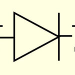
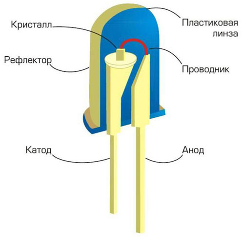
Design of an LED
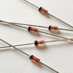
An LED was originally designed the same way as a conventional diode - a p-n junction and two leads. Only a body made of transparent compound or metal with a transparent window to observe the glow. But they learned how to build additional elements into the device shell. For example, Resistors - to turn on the LED in the circuit of the required voltage (12 V, 220 V) without external strapping. Or a generator with a divider to create flashing light-emitting elements. Also, the body was coated with a phosphor, which glows when the p-n junction is ignited - so it was able to expand the capabilities of LEDs.
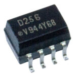
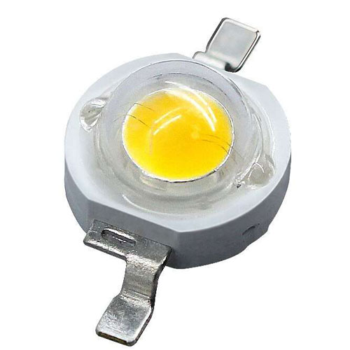
The trend of switching to lead-free radio elements has not left the LEDs. SMD devices are rapidly gaining market share in lighting technology, with the advantage of production technology. These elements have no leads. P-n junction is mounted on a ceramic base, filled with compound and coated with phosphor. Voltage is supplied through the contact pads.
Currently, lighting devices began to be equipped with LEDs made by COB-technology. The essence of it is that on one plate is mounted several (from 2-3 to hundreds) p-n junctions connected in a matrix. On top of everything is placed in a single housing (or formed an SMD module) and covered with phosphor. This technology has great prospects, but it is unlikely to completely displace other versions of LEDs.
What kinds of LEDs exist and where they are used
Optical range LEDs are used as indication elements and as lighting devices. For each specialty there are different requirements.
Indicator LEDs
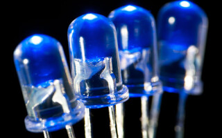
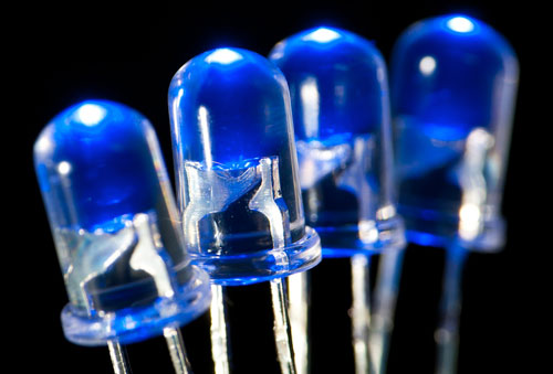
The task of an indicator LED is to indicate the status of a device (power supply, alarm, sensor actuation, etc.). LEDs with p-n junction glow are widely used in this field. Devices with phosphors are not prohibited to use, but there is no special point. Here the brightness is not in the first place. Contrast and wide viewing angle are a priority. On panels of devices used leds (true hole), on boards - led and SMD.
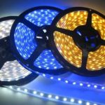
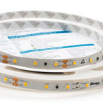
Lighting LEDs
For lighting, on the contrary, mostly elements with phosphors are used. This allows sufficient luminous flux and colors close to natural. The output LEDs from this area are practically squeezed out by SMD elements. COB LEDs are widely used.
In a separate category can be allocated devices designed to transmit signals in the optical or infrared range. For example, for remote control devices for household appliances or for security devices. And UV elements can be used for compact UV sources (currency detectors, biological materials, etc.).
The main characteristics of LEDs
Like any diode, LEDs have general, "diode" characteristics. Limit parameters, the excess of which leads to device failure:
- maximum allowable forward current;
- Maximum allowable forward voltage;;
- Maximum allowable reverse voltage.
The other characteristics are "diode" specific.
Color of glow
Color of luminescence - this parameter characterizes the optical range LEDs. In most cases, the luminaires are white with different light temperature. For indicator lights can be any of the visible color gamut.
Wavelength
This parameter to a certain extent duplicates the previous one, but with two reservations:
- devices in the IR and UV ranges do not have visible color, so for them this characteristic is the only one that characterizes the spectrum of radiation;
- this parameter is more applicable for LEDs with direct emission - elements with phosphors emit in a wide band, so their luminescence cannot be characterized unambiguously by wavelength (what wavelength can be in white color?).
Therefore, the wavelength of the emitted wavelength is a rather informative figure.
Current consumption
The current consumption is the operating current at which the brightness of the emission is optimal. If it is slightly exceeded, the device will not break down soon - and this is the difference from the maximum permissible. Lowering it is also undesirable - the intensity of radiation will drop.
Power
Power consumption - here everything is simple. On direct current it is simply the product of the current consumption by the voltage applied. Confusion in this concept is made by manufacturers of lighting, specifying on the packaging in large numbers equivalent power - the power of incandescent lamps, the luminous flux of which is equal to the flux of the lamp.
Visible solid angle
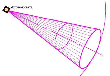
Visible solid angle is best represented as a cone coming from the center of the light source. This parameter is equal to the angle of opening of the cone. For indicator LEDs, it determines how the triggering of the alarm will be seen from the side. For illuminating elements, it determines the luminous flux.
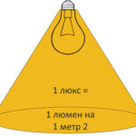
Maximum light intensity
The maximum light intensity in the technical specifications of the device is specified in candelas. But in practice it is more convenient to operate with the concept of luminous flux. Luminous flux (in lumens) is equal to the product of light intensity (in candelas) by the apparent solid angle. Two LEDs with the same light intensity give different light at different angles. The greater the angle, the greater the luminous flux. This is more convenient for calculating the lighting systems.
Voltage drop
Forward voltage drop is the voltage that falls on the LED when it is open. Knowing it, you can calculate the voltage required to open a series of light-emitting elements, for example.
How to know what voltage the LED is rated for
The easiest way to find out the rated voltage of an LED is to consult reference books. But if you got a device of unknown origin without marking, you can connect it to a regulated power supply and smoothly raise the voltage from zero. At a certain voltage the LED will flash brightly. This is the working voltage of the element. There are several nuances to keep in mind when doing this test:
- the device under test may be with a built-in resistor and designed for a sufficiently high voltage (up to 220 V) - not every power supply has such a regulation range;
- emission of LED may lie outside the visible part of the spectrum (UV or IR) - then the moment of ignition is not visually detectable (although the glow of the IR device in some cases can be seen through a smartphone camera);
- Connect the element to a DC voltage source with strict observance of polarity, otherwise it is easy to bring the LED out of operation with reverse voltage, exceeding the capabilities of the device.
If you are not sure about the element's pin, it is better to increase the voltage to 3...3.5V, if the LED did not light up - remove the voltage, reverse the connection of the source poles and repeat the procedure.
How to find out the polarity of the LED
There are several methods to determine the polarity of the leads.
- With leadless elements (including COBs), the polarity of the supply voltage is indicated directly on the case - by symbols or by tacks on the shell.
- Since the LED has a common p-n junction, it can be probed with a multimeter in diode test mode. Some testers have a measurement voltage sufficient to light the LED. Then the correct connection can be checked visually by the glow of the element.
- Some CCCP instruments in a metal case had a key (protrusion) near the cathode.
- With lead elements the cathode lead is longer. Only unsoldered elements can be identified by this feature. With used LEDs, the pins are shortened and bent for installation in any way.
- Finally, to find out the location of the anode and cathode is possible by the same method that is used to determine the voltage of the LED. The luminescence will only be possible if the element is properly turned on - cathode to the minus of the source, anode to the plus.
The development of technology does not stand still. A few decades ago, the LED was an expensive toy for laboratory experiments. Now it is hard to imagine life without it. What will be next - time will tell.
Related articles: