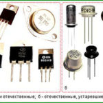
Field (unipolar) transistor is a device that has three outputs and is controlled by the applied control electrode (gate).gate) voltage is applied to the control electrode (gate). The regulated current flows through the source-drain circuit.
The idea of such a triode originated about 100 years ago, but it did not become possible to approach practical implementation until the middle of the last century. In the 1950s, the concept of a field-effect transistor was developed, and in 1960 the first working sample was produced. To understand the advantages and disadvantages of triodes of this type, it is necessary to understand their structure.
Contents
Design of Field Effect Transistors
Unipolar transistors fall into two large classes according to their design and manufacturing technology. While the control principles are similar, they have design features that determine their characteristics.
Unipolar triodes with p-n junction
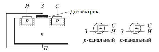
The structure of such a p-n junction transistor is similar to that of an ordinary semiconductor diode and, unlike its bipolar relative, contains only one junction. A p-n junction transistor consists of a wafer of one type of conductor (e.g., n), and an embedded region of another type of semiconductor (in this case, p).
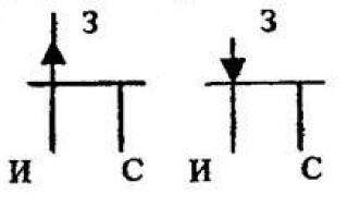
The n-layer forms a channel through which current flows between the pins of the source and the drain. The gate lead is connected to the p-region. If a voltage is applied to the gate shifting the transition in the opposite direction, the transition area expands, the channel cross-section, on the contrary, narrows, its resistance increases. By controlling the gate voltage, the current in the channel can be controlled. The transistor can also be made with a p-type channel, then the gate is formed by an n-semiconductor.
One of the peculiarities of this design is the very large input resistance of the transistor. The gate current is determined by the resistance of the reverse-switched junction, and is in the range of units or tens of nanamperes at DC. On AC current the input resistance is given by the junction capacitance.
The amplification stages assembled on such transistors, due to the high input impedance, simplify the matching with the input devices. Also, unipolar triodes do not recombine charge carriers, which reduces low-frequency noise.
When there is no bias voltage, the channel width is greatest and the current through the channel is maximum. When the voltage is increased, it is possible to reach a state of the channel where it is fully latched. This voltage is called the cutoff voltage (Uots).
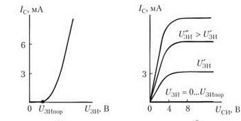
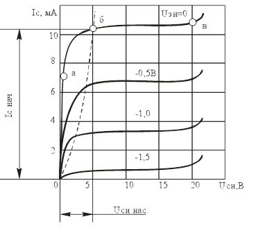 The drain current of a field effect transistor depends on both the voltage between gate and source and the drain-source voltage. If you fix the gate voltage, the current increases almost linearly with increasing Uci at first (ab plot). When entering saturation, a further increase in voltage causes practically no increase in drain current (bb section). As the level of the gate locking voltage increases, saturation occurs at lower values of I-stock.
The figure shows a family of voltage dependencies of the drain current between the source and the drain for several values of the gate voltage. Obviously, at Uci above the saturation voltage, the drain current depends practically only on the gate voltage.
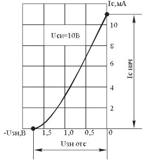 This is illustrated by the transfer characteristic of the unipolar transistor. As the negative gate voltage increases, the drain current decreases almost linearly until it reaches zero when the gate voltage reaches the cutoff voltage level.
Unipolar triodes with isolated gate
Another variant of a field effect transistor is the design with an insulated gate. These triodes are called TFTs TIR (metal-dielectric-semiconductor) transistors, foreign designation MOSFET. It used to be customary to call MOS (metal-oxide-semiconductor).
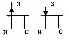
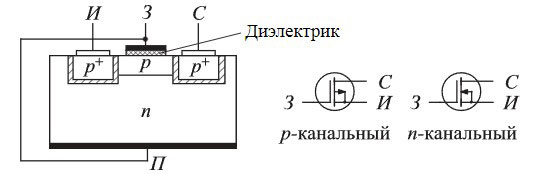 The substrate is made of a conductor of a certain conductivity type (in this case, n), the channel is formed by a semiconductor of another conductivity type (in this case, p). The gate is separated from the substrate by a thin dielectric (oxide) layer, and can affect the channel only through the electric field created. When the gate voltage is negative, the generated field displaces electrons from the channel area, the layer becomes depleted, and its resistance increases. For transistors with a p-type channel, on the contrary, the application of a positive voltage leads to an increase in resistance and a decrease in current.
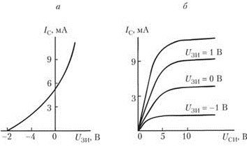 Another feature of a gate-isolated transistor is the positive portion of the transfer characteristic (negative for a p-channel triode). This means that a positive polarity voltage of a certain value can be applied to the gate as well, which will increase the drain current. The family of output characteristics is not fundamentally different from that of the p-n junction triode.
The dielectric layer between gate and substrate is very thin, so TIR transistors of early years of manufacture (for example, domestic KP350) were extremely sensitive to static electricity. High voltages punctured the thin film, rendering the transistor inoperable. In modern triodes, constructive measures have been taken to protect against overvoltage, so precautions against static are almost unnecessary.
 Another variant of the unipolar triode with an insulated gate is the induced-channel transistor. It does not have an inductive channel, so no current will flow from the source to the drain in the absence of voltage at the gate. If a positive voltage is applied to the gate, the field it generates "pulls" electrons from the n-zone of the substrate, and creates a channel in the near-surface region for current to flow. It is clear from this that such a transistor, depending on the type of channel, is controlled by voltage of only one polarity. This can also be seen from its pass-through characteristic.
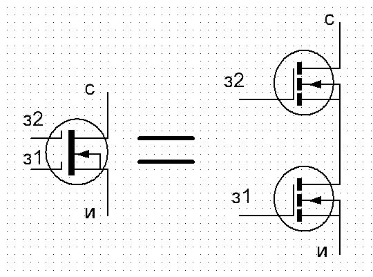
There are also double gate transistors. They differ from conventional ones in that they have two equal gates, each of which can be controlled by a separate signal, but their effect on the channel is summed up. Such a triode can be represented as two ordinary transistors in series.
Wiring Diagrams for Field Effect Transistors
The scope of application of field effect transistors is the same as for bipolar .. They are mainly used as amplifier elements. Bipolar triodes, when used in amplifier stages, have three basic circuits:
- common-collector (emitter repeater);
- with a common base;
- common emitter.
Field effect transistors are connected in a similar way.
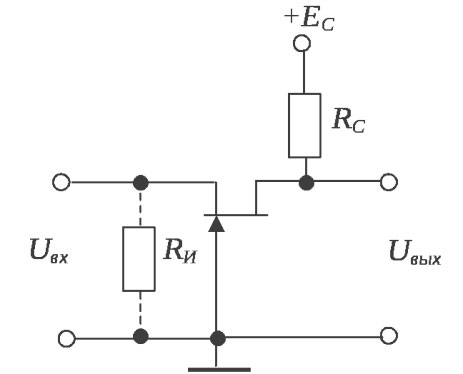
Common Stock Array
A common-drain circuit (Source Repeater), just like an emitter repeater on a bipolar triode, does not provide any voltage gain, but does provide current gain.
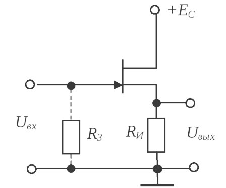
The advantage of the circuit is its high input resistance, but in some cases it is a disadvantage - the stage becomes sensitive to electromagnetic interference. If necessary, Rin can be reduced by including a resistor R3.
Circuit with common gate
This circuit is similar to a bipolar transistor with a common base. This circuit gives good voltage gain, but no current gain. Like the common base design, it is not commonly used.
Common Source Array
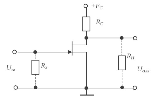 The most common circuit is the common source connection of field effect triodes. Its gain depends on the ratio of resistance Rc to resistance in the drain circuit (for adjusting the gain in the drain circuit an additional resistor can be installed) and also depends on the slope of the transistor characteristic.
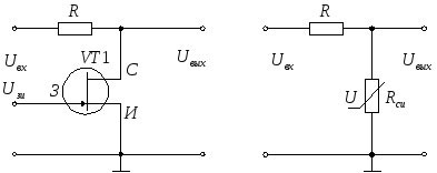
Field-effect transistors are also used as a controlled resistance. For this purpose, the operating point is chosen within the linear section. A controlled voltage divider can be implemented according to this principle.
And on a double gate triode in this mode you can implement, for example, a mixer for the receiving equipment - on one gate the received signal, and on the other - the signal from the heterodyne.
If you accept the theory that history evolves in a spiral, you can see a pattern in the development of electronics. The technology moved away from voltage-controlled tubes to bipolar transistors, which need current to control them. The spiral has made a complete turn - now there is a dominance of unipolar triodes, which do not require, like lamps, power consumption in the control circuits. Where the cyclic curve will take us next - we will see. So far, no alternative to field-effect transistors has been observed.
Related articles: