Electrical installation and commissioning always involves measuring the characteristics of an electrical network, checking the presence of voltage and the serviceability of the circuits of an appliance or line. For this purpose there is a huge number of different measuring devices and testers, but the most universal and useful device for home masters and professionals is a multimeter. In this article we will consider how to use it.
Contents .
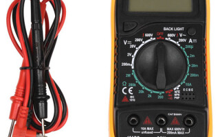
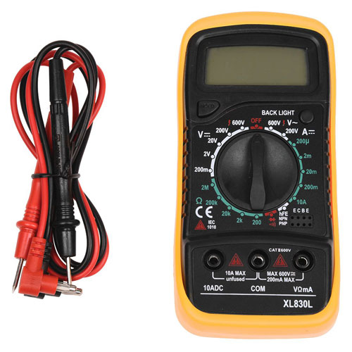
Multimeter appearance
Multimeter - is a universal device for measuring electrical characteristics, which combines many functions (depending on the model). The minimum configuration consists of an ammeter, a voltmeter and an ohmmeter. The most common version is a digital handheld version. It has a rectangular shape with a display and a rotary or pushbutton function switch. To make measurements, two probes are connected to the multimeter (red and black) in strict accordance with the marking on the device.
Brief description of the parameters to be measured and their designation
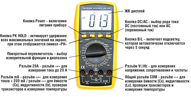
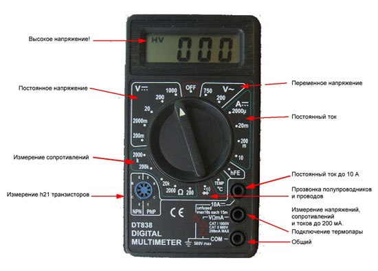
Manufacturers use standard markings in English or special symbols to indicate parameters on multimeters. To work with the device it is important to know the basics of electrical engineering in order to perform the necessary measurements correctly and safely.
Each instrument is divided into zones with settings for working with a specific type of voltage of the electrical network:
- ACV or V~ - AC voltage;
- DCV or V- - DC voltage;
- DCA or A- - DC current strength;
- Ω - is the resistance in the circuit section or in the electrical device.
Assignment of stylus connectors
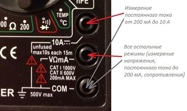
Depending on the model of the multimeter, the number of stylus connectors varies. The probes for measuring the electrical parameters of the mains must be connected to the correct sockets of the device. The marking of the sockets in most measuring devices is as follows:
- 10А- - for measuring DC current not exceeding 10A (the red plus probe is connected to this socket);
- VΩmA or VΩ, V/Ω - plugged into this socket the red (plus) probe for determining voltage, DC current up to 200 mA, for diode and circuit testing;
- COMMOM (COM) - This is a common socket for the blackminus) probe on all types of multimeters;
- 20А - not all multimeters have this socket (most often found on expensive professional devices), the task of this socket is the same as the 10A socket but with a limit up to 20A.
What other buttons can be
In addition to the basic settings of the multimeter, it can have additional settings. Expensive professional devices are much more functional than budget versions and allow the technician to make the following measurements:
- AC current (in the presence of clamp meters);
- circuit continuity (probe), i.e. checking the resistance by means of acoustic or visual alarms or indications on the display;
- testing the functionality of diodes (switch ->Ι-);
- transistor parameters (connectors and buttons with hFE designation);
- capacitance and inductance;
- temperature (an external sensor, usually a thermocouple, is used for this).
- frequency (Hz).
Some models have additional functions for displaying and operating the device: backlight, auto power-off and power-saving mode for the battery, recording results (button hold) and recording in the device memory, selection of measurement limits and overload and low battery indication. For safe operation of the multimeter it is important that the instrument has some protection in case of incorrect selection of measurement limits or mode of operation. This protection is usually provided by fuses and circuit breakers. Most quality instruments from responsible manufacturers have this protection.
How to measure voltage
For someone who has some skills and knowledge of electrical engineering, it should not be too difficult to take measurements with a multimeter. For those who have never worked with this type of device, below is how to use a standard multimeter.
Important! All work should be carried out by specialists or people with specific electrical engineering skills. Remember that electrocution is dangerous to life!
Constant Voltage
This mode is used to measure the voltage of power cells, batteries and car batteries. Most control circuits in modern ACS systems have a potential of 24 V DC.
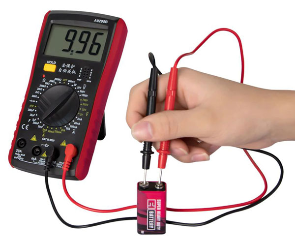
In order to make a measurement in this mode you must put the device in the DCV position and measure (unless you know the approximate voltage) it is best to start with the maximum value of the switch, gradually decreasing the range, until you get the desired dimension. If the screen of the device shows the measurement result with the "minus" sign, it means that the polarity of the probes is wrong (this means that the "minus" was connected to the "plus" of the measuring circuit and the "plus" to the "minus".).
As for the dimensions, everything is simple: if, for example, the number 003 appears on the screen, it means that it is necessary to reduce the measurement range. Gradually decreasing the voltage value with the switch, 03, 3 will be displayed.
If the display shows "1" or another incomprehensible number, most likely the operating mode is not correct or the upper limit of the measured voltage needs to be increased. In other words, the measured voltage value should be lower than the upper limit selected on the multimeter.
The standard values for the switch in the DC voltage zone are: up to 200mV, 2V, 20V, 200V, 1000V.
Please note! It will most likely not be possible to make a voltage measurement on a thermocouple that is only a few millivolts because of the error of the multimeter.
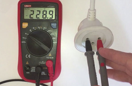
AC Voltage
The AC voltage measurement mode is activated by moving the switch to the V~ or ACV position. This mode also has several ranges. Typically on standard multimeters there are two AC voltage selections: up to 200 V and up to 750 V.
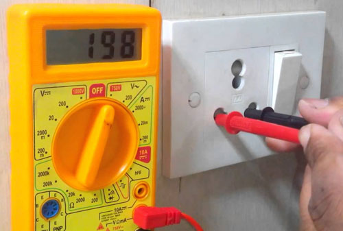
For example, to measure the voltage in a 220V household network, set the switch to 750V and insert two probes into the socket (into different holes). The display will show the actual voltage at the current moment of time. Usually it is between 210 and 230 V, other readings are already deviations from the norm.
Measuring the amperage
To do this, you need to know what kind of current will be measured: direct or alternating. Most standard multimeters can measure DC, but for AC you need a multimeter with a clamp meter.
Direct Current
To do this, move the multimeter switch to DCA mode. The red probe must be connected to the socket marked "10 A" and the black one to "COM". If the value of the measured current is up to 200 mA, then for more accurate readings, move the red probe to the socket marked 200 mA. In any case, in order not to burn the device, it is best to start measuring with the probe in the 10A connector and move it if necessary. We do the same with the switch: first we set the highest current, gradually decreasing the range to get the desired maximum limit to the minimum value of 2000 microamperes.
Note! To measure a direct electric current, the multimeter probes are placed in the circuit gap.
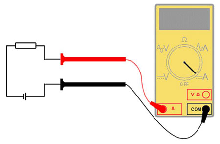
It is important to know that the multimeter probes are connected in the circuit break. That is, the red probe is placed on the "plus" of the power source, and the black probe is placed to the "plus" conductor.
Alternating Current
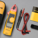
The value of alternating current can be measured with a multimeter that has special current clamps.
The principle of the clamp meter is based on the phenomenon of electromagnetic induction. The measurement is made in a non-contact way by placing a conductor in the electromagnet with the secondary winding. Primary current (measured by), is proportional to the secondary current (which arises on the winding). Therefore, the device can easily calculate the desired primary AC value.
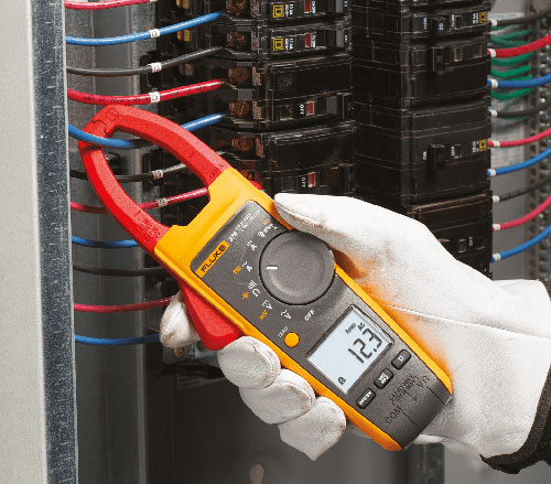
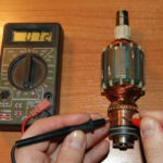
During the measurement the maximum limit is set (in the same way as a direct current measurement), the conductor is led inside the clamps as in the picture above and the screen shows the measured value in amperes.
Measuring the resistance
To measure resistance the switch is set to resistance mode (Ω) and the desired range is selected. One of the probes is attached to one input of the resistor, the other to the other one. At that the resistance value will be shown on the display. By switching the range you can get the desired resistance value dimension.
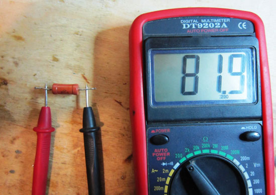
If "zero" appears on the display, the range should be decreased, and if "1", the range should be increased.
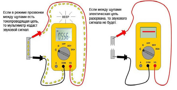
How to test wires with a multimeter
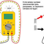
Wire-checking means determining the continuity of the wires. Essentially a multimeter determines the resistance of a closed circuit and if this value is close to zero, the circuit is considered closed and an audible signal is emitted. Not every multimeter can test wires with a sound, but most can.
A continuity test is a test of the continuity of a circuit. The multimeter is set in the right mode to test the wires. Most often it is combined with the diode test, but it can also be separate and marked with a bell symbol. Next, one probe is attached to one end of the conductor and the other probe to the other end. This sounds a tone or indication appears in the light or on the display. If there is an indication - the circuit is not broken, if not, then the conductor is damaged or the circuit is broken.
Checking Diodes, Capacitors, and Transistors (hFE Mode)
Not every device has this mode. To check the resistance of diodes, select the appropriate mode and by analogy with the wire tester perform the necessary actions.
To determine the parameters of capacitors and transistors a special mode "hFE».
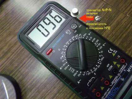
Transistors have three outputs: base, emitter and collector, which are connected to sockets B, E, F of the multimeter. When properly connected the display will show the amplification value of the transistor.
With capacitors the capacitance is measured by inserting the capacitor ends into the connectors marked Cx. The display will show the nominal value of the electronic component's capacitance.
Related articles: