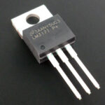
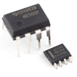
KPEN, "krenka" - the household name for 142 series integrated voltage regulators. The size of its housing does not allow for the full marking of the series (KR142EN5A, etc.), so the developers were limited to a short version - KPEN5A. "Krenks" are widespread both in industry and in amateur practice.
Contents
What are the voltage regulators KPEN 142
Microcircuits series 142 gained popularity because of the simplicity of obtaining a stable voltage - a simple strapping, lack of adjustment and settings. It is enough to apply power to the input, and get a stabilized voltage at the output. The most popular and widespread are unregulated integrated regulators in packages TO-220 for voltages up to 15 volts:
- KR142EN5A, V - 5 volts;
- KR142EN5B, G - 6 volts;
- KR142EN8A, G - 9 volts;
- KR142EN8B, D - 12 volts;
- KR142EN8B, E - 15 volts;
- KR142 ЕН8Ж, I - 12.8 volts.
In cases where a higher stable voltage is needed, the devices are used:
- KR142EN9A - 20 volts;
- KR42EN9B - 24 volts;
- KR142EN9B - 27 volts.
These chips are also available in a planar design with slightly different electrical characteristics.
The 142 series includes other integrated regulators. К chips with adjustable output voltage include:
- KR142EN1A, B - with a regulation range of 3 to 12 volts;
- The KR142EN2B - with a range of 12...30 volts.
These devices are produced in packages with 14 pins. This category also includes three-pin stabilizers with the same output range of 1.2 to 37 volts:
- KR142EN12 positive polarity;
- KR142EN18 negative polarity.
The series includes a chip KR142EN6 - bipolar regulator with the ability to regulate the output voltage from 5 to 15 volts, as well as inclusion as an unregulated source of ±15 volts.
All elements of the series have built-in protection against overheating and short circuit at the output. And polarity reversal on the input and the application of an external voltage to the output they do not like - the lifetime in such cases is counted in seconds.
Chip modifications
The modifications of the chips that make up the series differ in their enclosure. Most of the unipolar unregulated regulators are made in a "transistor" TO-220 package. It has three pins, which is not sufficient in all cases. Therefore, some chips were made in multiple lead packages:
- DIP-14;
- 4-2 - the same but in a ceramic shell;
- 16-15.01 - planar case for surface mounting (SMD).
Such versions are mainly available in adjustable and bipolar stabilizers.
Main technical characteristics
In addition to the output voltage, what is important for the regulator is the current it can provide under load.
| Chip type | Rated current, А |
|---|---|
| К(Р)142ЕН1(2) | 0,15 |
| K142EN5A, 142EN5A | 3 |
| KR142EN5A | 2 |
| K142EN5B, 142EN5B | 3 |
| KR142EN5A | 2 |
| K142EN5V, 142EN5V, KR142EN5V | 2 |
| K142EN5G, 142EN5G, CR142EN5G | 2 |
| K142EN8A, 142EN8A, CR142EN8A | 1,5 |
| K142EN8B, 142EN8B, CR142EN8B | 1,5 |
| K142EN8C, 142EN8C, CR142EN8C | 1,5 |
| KR142EN8G | 1 |
| KR142EN8D | 1 |
| KR142EN8E | 1 |
| KR142EN8G | 1,5 |
| KR142EN8I | 1 |
| K142EN9A, 142EN9A | 1,5 |
| K142EN9B, 142EN9B | 1,5 |
| K142EN9B, 142EN9B | 1,5 |
| KR142EN18 | 1,5 |
| KR142EN12 | 1,5 |
This data is sufficient for a preliminary decision on the possibility to use a particular regulator. If additional characteristics are needed, they can be found in reference books or on the Internet.
Pin assignment and operating principle
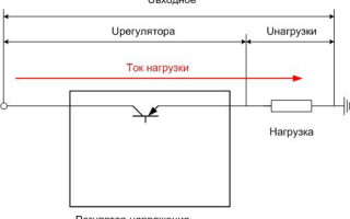
On the principle of operation all microcircuits of the series belong to line regulators. This means that the input voltage is distributed between the regulating element (transistor) of the stabilizer and the load, so that the voltage drops on the load, which is set by the internal elements of the chip or external circuits.
If the input voltage increases, the transistor closes, if it decreases - it opens so that the voltage at the output remains constant. When the load current changes, the regulator operates in the same way, keeping the load voltage constant.
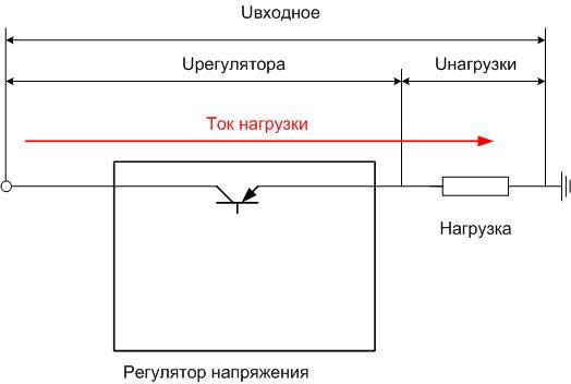
This circuit has disadvantages:
- Through the regulating element is constantly flowing load current, so it is constantly dissipated power P=Uof the regulator⋅Ithe load. This power is wasted and limits the efficiency of the system - it cannot be higher than Uload/ Uof the regulator ..
- The input voltage must be higher than the stabilizing voltage.
But the ease of use, the cheapness of the device outweighs the disadvantages, and in the range of operating currents up to 3 A (and even above) something more complicated is pointless to use.
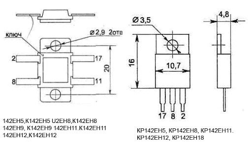
The voltage regulators with fixed voltage, as well as regulated regulators of new developments (K142EN12, K142EN18) in three- and four-lead versions have pins designated by numbers 17,8,2. Such illogical combination is obviously chosen for matching of pins with microcircuits in DIP packages. In fact, such a "dense" marking has remained only in the technical documentation, while the schemes are used by the terminal designations corresponding to foreign counterparts.
| Symbols in Technical Documentation | Pin assignment on diagrams | Pin assignment | ||
|---|---|---|---|---|
| Fixed Voltage Stabilizer | Stabilizer with adjustable voltage | Fixed Voltage Stabilizer | Stabilizer with adjustable voltage | |
| 17 | In | Input | ||
| 8 | GND | ADJ | Common wire | Reference voltage |
| 2 | Out | Output | ||
Older K142EN1(2) microcircuits in 16-pin planar packages have the following pin assignment:
| Assignment | Pin number | Pin number | Designation |
|---|---|---|---|
| Not used | 1 | 16 | Input 2 |
| Noise filter | 2 | 15 | Not used |
| Not used | 3 | 14 | Output |
| Input | 4 | 13 | Output |
| Not used | 5 | 12 | Voltage regulation |
| Reference voltage | 6 | 11 | Current protection |
| Not used | 7 | 10 | Current protection |
| General | 8 | 9 | Switching off |
A disadvantage of the planar design is a large number of redundant device outputs.
The KR142EN1(2) stabilizers in DIP14 packages have a different pin assignment.
| Designation | Pin number | Pin number | Designation |
|---|---|---|---|
| Current protection | 1 | 14 | Switching off |
| Current protection | 2 | 13 | Correction circuits |
| Feedback | 3 | 12 | Input 1 |
| Input | 4 | 11 | Input 2 |
| Reference voltage | 5 | 10 | Output 2 |
| Not used | 6 | 9 | Not used |
| Common | 7 | 8 | Output 1 |
K142EN6 and KR142EN6 microcircuits, produced in different housing versions with heat sink and single-row layout of the pins, have the following pinout:
| Pin number | Designation |
|---|---|
| 1 | Control signal input of both arms |
| 2 | Output "-" |
| 3 | Control "-" input |
| 4 | Common |
| 5 | Correction "+" |
| 6 | Not used |
| 7 | Output "+" |
| 8 | Input "+" |
| 9 | Correction "-" |
Example of a typical connection diagram
The typical circuit is the same for all unregulated single-phase voltage regulators:
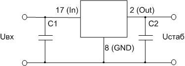
C1 must have a capacity from 0.33 μF, C2 from 0.1. A rectifier filter capacitor can be used as C1 if the conductors from it to the stabilizer input have a length not exceeding 70 mm.
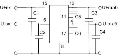
The K142EN6 bipolar stabilizer is usually switched like this:
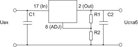
For the K142EN12 and EN18 chips, the output voltage is set with resistors R1 and R2.
For K142EN1(2) the typical circuit looks more complicated:
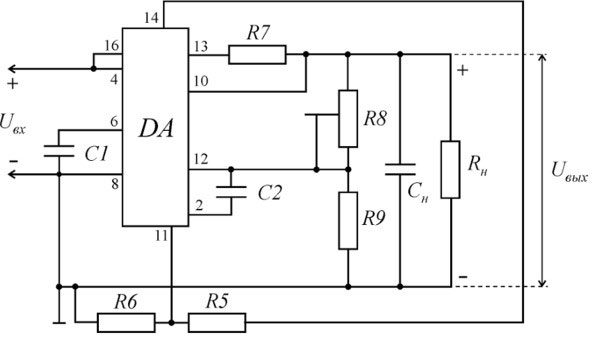
In addition to the typical integrated circuit for the 142 series stabilizers, there are other options that allow you to expand the scope of application of the chips.
What are the analogs
For some 142 series devices there are full foreign analogs:
| K142 chip | Foreign analog |
|---|---|
| KREN12 | LM317 |
| KPP18 | LM337 |
| KPHN5A | (LM)7805C |
| CREN5B | (LM)7805C |
| CREN8A | (LM)7806C |
| CREN8B | (LM)7809C |
| KPHEN8B | (LM)78012C |
| KPHEN6 | (LM)78015C |
| KPHEN2B | UA723C |
Full analog means that the microcircuits are identical in electrical characteristics, package and pin layout. But there are also functional analogs, which in many cases replace the design chip. So, 142EN5A in a planar package is not a full analogue of 7805, but it corresponds to it in terms of characteristics. Therefore, if it is possible to install one case instead of the other, such a replacement will not degrade the quality of the whole device.
Another situation is that the KREN8G in the "transistor" version is not considered an analogue of the 7809 due to the fact that it has a lower stabilization current (1 amp vs. 1.5 amps). If it is not critical and the actual current consumption in the supply circuit is less than 1A (with reserve), then you can safely replace the LM7809 with the KR142EN8G. And in each case, you should always resort to the help of a reference book - often you can pick up something similar in functionality.
How to Test the Functionality of KREN Chips
The 142 series microcircuits have a rather complicated structure, so it is impossible to uniquely check its functionality with a multimeter. The only way is to assemble a real switch layout (on the board or in a hinged mounting), which includes at least input and output capacitors, apply power to the input and check the voltage at the output. It must correspond to the passport value.
Despite the dominance of foreign-made microcircuits on the market, the 142 series devices retain their position due to the quality of manufacturing and other consumer properties.
Related articles:
