Sensors - the transducers of one physical quantity to another (usually, electrical) are widely used in household and industrial appliances. Without them it is very difficult, if not impossible, to measure, digitize and process such technological parameters as pressure and flow rate (gas or liquid), temperaturelevel, strength of magnetic or electric fields, etc. One of the most widespread sensors is the Hall sensor - it is used both in everyday life (starting with smartphones or laptops) and in the most complex industrial equipment.
Contents
 The Hall effect - the principle of operation
The effect was discovered in 1879 by the American physicist Edwin Hall and is named after him. The essence of the phenomenon is that if you take a metal plate and pass an electric current through it (in the direction AB in the figure), and then act on the plate with a magnetic field, for example, created by a permanent magnet, then in the direction perpendicular to the passage of current (CD in the figure), a potential difference will occur.
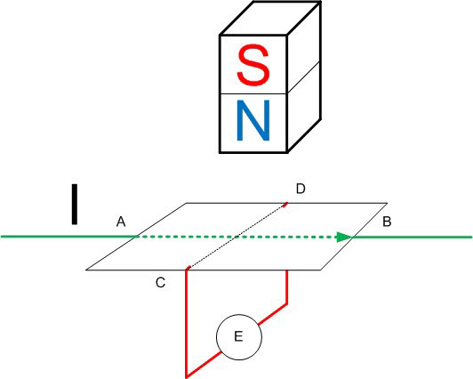
This effect arises due to the Lorentz force acting on the moving charges and shifting them in the direction perpendicular to the direction of motion. As a result, a potential difference arises at the edges of the plate, which can be measured or used to actuate actuators (by preamplifying). This difference depends on:
- on the strength of the current flowing;
- the strength of the magnetic field;
- on the concentration of free charge carriers in the conductor.
The phenomenon is named after its discoverer - the Hall effect.
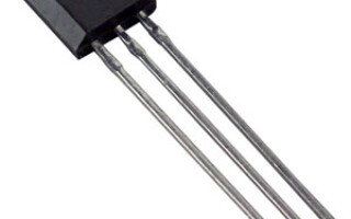
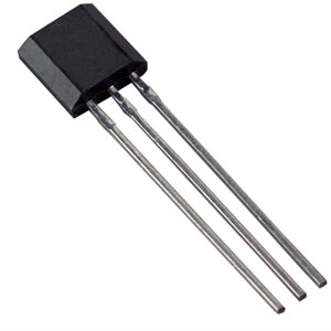
Types and construction of Hall sensors
The effect discovered as far back as the century before last has found a practical application. It is the basis for the construction of magnetic field sensors. Their advantage is that they have no moving and rubbing elements (unlike reed switches), so their reliability is much higher. According to the principle of sensitivity industrial sensors Hall are divided into:
- unipolar (react only to one magnetic pole - north or south);
- bipolar (they are switched on upon exposure to a magnetic field of one polarity, they are switched off upon exposure to a magnetic field of the opposite polarity);
- Omnipolar - reacts to any pole of the magnets.
The potential difference created by a magnetic field on moving charges is units, at best tens of microvolts. For practical applications, this is not enough, the potential difference must be amplified. These amplifiers are built directly into the sensor housing, and the devices are divided into two classes according to the type of amplifier.
- Analog. In them, the voltage at the sensor output is proportional to the magnetic field (depends on the strength of the magnet and the distance from it). They are built on the basis of an operational amplifier and are used to measure magnetic fields.
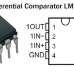
- Digital. After the amplifier is installed comparator or a Schmitt trigger. The output voltage, when magnetic induction reaches a certain threshold, changes from zero to a high level (usually to the supply voltage level). Such sensors are used to build magnetic relays or pulse generators. The amplified signal from the plate is fed to the threshold device. When the set level is reached, the sensor triggers. The triggering level can be adjusted by changing the distance from the sensor to the magnetic field source.
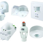
Hall sensor applications
The most common application of the Hall sensor in the home is in the contactless ignition systems of the car. Their advantage is the absence of mechanical contact groups. This means no wear, no burning of contacts, no risk of mechanical breakdown.
The distribution system contains a plate with protrusions, driven in rotation by the engine crankshaft, a permanent magnet and the Hall sensor itself. As the plate rotates, the projections at a strictly defined moment, determined by the position of the crankshaft, enter the gap between the sensor and the magnet, changing the parameters of the magnetic field. The sensor generates pulses, synchronized with the rotation of the crankshaft, which regulate the voltage supply to the high-voltage coil at the necessary moments of time. Magnetic field sensors in the vehicle are also used to recognize the position of the crankshaft.
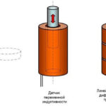
Another use of magnetically sensitive sensors is to determine the position of electric motor rotors. The relay element is attached to the motor stator and is triggered when the pole is passed. This principle can be used to build a revolution counter or a speed meter.
Devices based on the Hall effect are used in laptops or mobile devices - as an indicator of the closed position of the lid. When the sensor is triggered, the computer goes to sleep or shuts down. And in smartphones, one of the functions of the sensor that reacts to the Earth's magnetic field is to organize the operation of the electronic compass.
Analog Hall sensors are used in measuring instruments where it is necessary to estimate the magnetic field level. They are indispensable for non-contact measurement of current in a conductor. As you know, when current flows through a conductor, a magnetic field arises around it. Its intensity depends on the current strength. If the current is alternating, the field can be measured by other means (e.g. a current transformer), but with direct current you can't do without a Hall sensor. This is the principle on which DC current clamps work.
The most exotic application of the Hall effect is the construction of ion rocket engines based on its principle.
How to test a Hall sensor for proper functioning
To test the sensor, you can assemble a simple circuit, for which, in addition to the sensor itself, you will need:
- A power supply with the right voltage;
- resistor resistance of about 1 kOhm;
- LED;
- magnet.
If there is no LED, you can use a multimeter instead (and a current limiting resistor). multimeter (digital or pointer) in the voltage measurement mode.
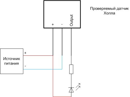
There are no special requirements to the power supply - the currents in the circuit are quite small. Its voltage must be within the supply voltage of the tested sensor. The LED is connected with the anode to the plus of the voltage source, with the cathode to the output of the device under test, because the sensor is usually made with an open collector (but it is better to check with the datasheet).
The test procedure depends on the type of device under test.
- To test a unipolar digital sensor, you must bring a magnet with one pole to the sensor. The LED should light up (the arrow of the voltmeter should deflect or the reading of the digital tester should change by leaps and bounds). When the magnet is removed at a considerable distance, the circuit should return to its original position. If the sensor does not work, you should turn the magnet with the other pole and repeat the procedure. If the LED flashes, then the sensor is good. If success is not achieved in any position of the magnet, the device is unsuitable for operation.
- Bipolar digital sensor is tested by a similar method, only the LED lights up at one position of the magnet, and does not go out when the source of the magnetic field is removed. The circuit should not respond to further manipulation with the same pole. If you turn the magnet over and bring it to the sensor in the opposite polarity, the LED should go off. This indicates that the device under test is working properly. If the circuit is not working properly, then the sensor is out of order.
- An omnipolar digital Hall sensor is tested in the same way as a unipolar sensor, but the magnet-sensitive device should actuate at any magnet position.
Analog sensors are tested using the same technique as digital sensors, but the output voltage should not change by leaps and bounds, but smoothly as the magnetic force increases (e.g. approaching a permanent magnet or increasing current in the coil of the electromagnet).
On the practical side, it is interesting how to check the Hall sensor installed in the contactless ignition system of the car. To do this, you have to remove the connector from the sensor and assemble the above circuit directly on the pins.
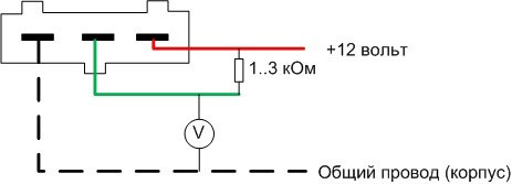
Here also the LED can be replaced by a multimeter. By turning the car's crankshaft manually, you can observe intermittent LED flashes or changes of output voltage from zero to approximately the on-board voltage of the car. An alternative way to check in garage conditions is to temporarily replace the device with a known faulty spare sensor.
The Hall sensor has found widespread use in domestic and industrial applications. It is not difficult to check it if you have an understanding of how it works.
Related articles: