Temperature is one of the main physical parameters. It is important to measure and control it both in everyday life and in production. There are many special devices for this purpose. The resistance thermometer is one of the most common instruments used extensively in science and industry. Today we will tell you what a resistance thermometer is, its advantages and disadvantages, as well as understand the different models.
Contents
Area of Application
An resistance thermometer - is a device designed to measure the temperature of solid, liquid and gaseous media. It is also used to measure the temperature of bulk solids.
Its place resistance thermometer found in the gas and oil production, metallurgy, energy, utilities and many other industries.
IMPORTANT! Resistance thermometers can be used in neutral environments as well as in aggressive ones. This contributes to the spread of the instrument in the chemical industry.
Please note! For measuring temperatures in industry thermocouples are also used, about them learn more from in our article about thermocouples.
Types of sensors and their characteristics
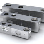
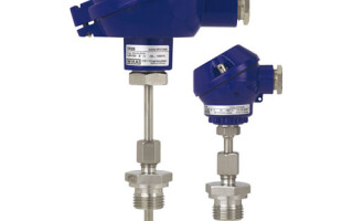
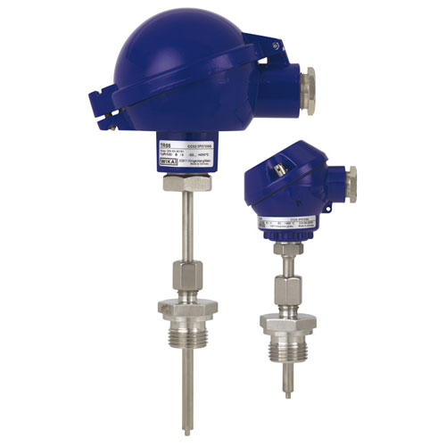
Measuring temperature with a resistance thermometer involves one or more resistance sensing elements and connecting wires, which are securely hidden in a protective housing.
RTDs are classified according to the type of sensing element.
Metal resistance thermometer according to GOST 6651-2009
According to GOST 6651-2009 There is a group of metallic resistance thermometers, that is, TS, whose sensitive element - it is a small resistor of metal wire or film.
Platinum temperature meters
Platinum RTDs are considered the most common among the other types, so they are often installed to monitor important parameters. The temperature measurement range is from -200 °C to 650 °C. The characteristic is close to a linear function. One of the most common types is Pt100 (Pt is platinum, 100 means 100 ohms at 0 °C).
IMPORTANT! The main disadvantage of this device - expensive due to the use of precious metal in the composition.
Nickel resistance thermometers
Nickel resistance thermometers are almost not used in production because of the narrow temperature range (from -60 °С to 180 °С) and complexity of operation, however, it should be noted that they have the highest temperature coefficient 0,00617 °С-1.
Earlier such sensors were used in shipbuilding, however, now in this industry they have been replaced by platinum RTDs.
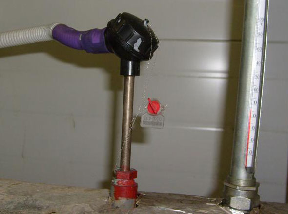
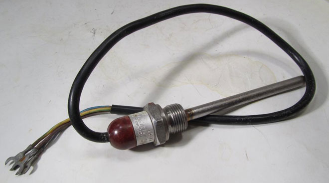
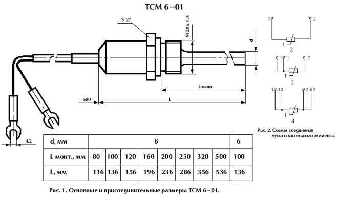
Copper Sensors (TCM)
It would seem that copper sensors have an even narrower range of use than nickel sensors (only from -50 °C to 170 °C), but, nevertheless, they are more popular type of TCS.
The secret is in the cheapness of the device. Copper sensing elements are simple and unpretentious in use, and excellent for measuring low temperatures or related parameters, such as the air temperature in the shop.
The service life of such a device is short, however, and the average cost of copper RTDs does not hit the pocket too hard (about 1 thousand rubles).
Thermal resistors
Thermoresistors are resistance thermometers, whose sensitive element is made of a semiconductor. This can be an oxide, halide or other substances with amphoteric properties.
The advantage of this device is not only the high temperature coefficient, but also the ability to give any shape to the future product (from a thin tube to a device with a length of several microns). Typically thermistors are designed to measure temperature from -100 °С to +200 °С..
There are two types of thermistors:
- Thermistors - have a negative temperature coefficient of resistance, that is, when the temperature rises, resistance decreases;
- posistors - have a positive temperature coefficient of resistance, that is, with increasing temperature, resistance also increases.
Graduation tables for resistance thermometers
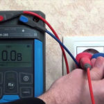
Graduation tables are a summary grid from which you can easily determine at what temperature a thermometer will have a certain resistance. Such tables help instrumentation workers estimate the value of the measured temperature from a certain resistance value.
Within this table, there are special RTD designations. You can see them on the top line. The number means the resistance value of the sensor at 0 ° C, and the letter the metal of which it is made.
For the designation of the metal use:
- P or Pt - platinum;
- М - copper;
- N - nickel.
For example, 50M is a copper RTD, with a resistance of 50 ohms at 0 °C.
Below is a fragment of the thermometer calibration table.
| 50M (Ohm) | 100M (Ohm) | 50P (Ohm) | 100P (Ohm) | 500P (Ohm) | |
|---|---|---|---|---|---|
| -50 °С | 39.3 | 78.6 | 40.01 | 80.01 | 401.57 |
| 0 °С | 50 | 100 | 50 | 100 | 500 |
| 50 °С | 60.7 | 121.4 | 59.7 | 119.4 | 1193.95 |
| 100 °С | 71.4 | 142.8 | 69.25 | 138.5 | 1385 |
| 150 °С | 82.1 | 164.2 | 78.66 | 157.31 | 1573.15 |
Tolerance class
Tolerance class should not be confused with accuracy class. With a thermometer, we do not directly measure and see the measurement result, but we transmit the resistance value corresponding to the actual temperature to the barriers or secondary devices. This is why a new concept has been introduced.
Tolerance class is the difference between the actual body temperature and the temperature obtained from the measurement.
There are 4 accuracy classes of TCs (From the most accurate to devices with a larger error):
- AA;
- А;
- B;
- С.
Here is a fragment of the table of tolerance classes, the full version you can see in GOST 6651-2009.
| Accuracy class | Tolerance, °С | Temperature range, °С | ||
|---|---|---|---|---|
| Copper TS | Platinum TS | Nickel TS | ||
| AA | ±(0,1 + 0,0017 |t|) | - | from -50°C to +250°C | - |
| А | ±(0,15+0,002 |t|) | from -50 °C to +120 °C | from -100 °C to +450 °C | - |
| В | ± (0,3 + 0,005 |t|) | from -50 °C to +200 °C | from -195 °C to +650 °C | - |
| С | ±(0,6 + 0,01 |t|) | -180 °C to +200 °C | -195 °C to +650 °C | -60 °C to +180 °C |
wiring diagram
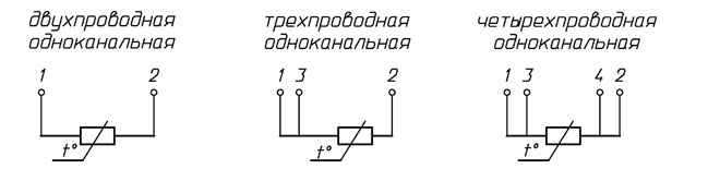
In order to know the value of resistance it must be measured. This can be done by including it in the measurement circuit. To do this, use three types of circuit, which differ from each other by the number of wires and the measurement accuracy achieved:
- 2-wire circuit. It contains the minimum number of wires and is therefore the cheapest option. However, this circuit will not achieve optimum accuracy - the resistance of the thermometer will be added to the resistance of the wires used, which will introduce an error that depends on the length of the wires. In industry, such a scheme is rarely used. It is only used for measurements where accuracy is not important and the sensor is in close proximity to the secondary transducer. 2-wire circuit shown in the left picture.
- 3-wire circuit. In contrast to the previous version, an additional wire is added here, short-circuited to one of the other two measuring wires. Its main purpose is is to be able to get the resistance of the connected wires and subtract this value (compensate) from the measured value from the sensor. The secondary device, in addition to the basic measurement, additionally measures the resistance between the closed wires, thus obtaining the resistance value of the connection wires from the sensor to the barrier or secondary device. Since the wires are closed, this value should be equal to zero, but in fact, due to the long length of the wires, this value can reach several ohms. Then this error is subtracted from the measured value, obtaining a more accurate reading, due to the compensation of the resistance of the wires. This connection is used in most cases, as it is a compromise between the required accuracy and an acceptable price. The 3 wire circuit is shown in the center picture.
- 4-wire circuit. The purpose is the same as with the 3-wire circuit, but error compensation goes to both measurement wires. In a three-wire circuit, the resistance value of both test leads is assumed to be the same value, but in fact it may differ slightly. By adding another fourth wire in a four-wire circuit (shorted to the second test lead), it is possible to get its resistance value separately and almost completely compensate all of the resistance from the wires. However, this circuit is more expensive as a fourth conductor is required and is therefore implemented either in companies with sufficient funding, or when measuring parameters where greater accuracy is needed. The 4-wire connection diagram you can be seen in the figure on the right.
Please note! The Pt1000 sensor already has a resistance of 1000 ohms at zero degrees. You can see them, for example, on the steam pipe, where the measured temperature is equal to 100-160 ° C, which corresponds to about 1400-1600 Ohm. The resistance of the wires depending on the length is about 3-4 ohms, i.e. they practically do not influence the error and there is no point in using a three-wire or four-wire connection scheme.
Advantages and disadvantages of resistance thermometers
Like any device, the use of resistance thermometers has a number of advantages and disadvantages. Let's look at them.
Advantages:
- practically linear characteristic;
- the measurements are sufficiently accurate (error no more than 1 ° C.);
- some models are cheap and easy to use;
- interchangeability of devices;
- stability of operation.
Disadvantages:
- small measuring range;
- rather low limiting temperature of measurements;
- The need to use special connection schemes for increased accuracy, which increases the cost of implementation.
The resistance thermometer is a common device in almost all industries. It is convenient for measuring low temperatures without fearing for the accuracy of the data obtained. The thermometer is not particularly durable, but the reasonable price and ease of sensor replacement override this small disadvantage.
Related articles: