To conveniently control lighting fixtures and reduce the cost of electricity use, users are increasingly resorting to the use of automatic control devices based on motion sensors of various configurations. Installation of such devices is made according to certain schemes, which we will consider in this article.
Contents .
Choosing where to install the motion detector
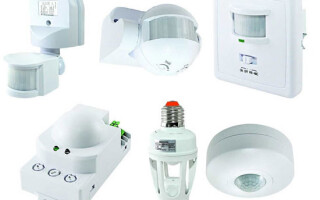
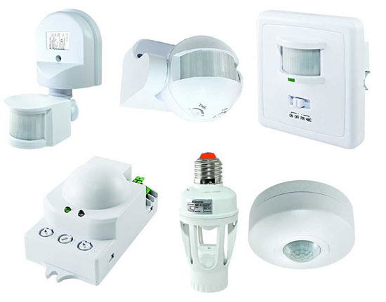
The first thing to do after purchasing a motion detector is to decide where to install it. Choosing the right location is very important for the correct operation of the motion sensor and preventing false alarms.
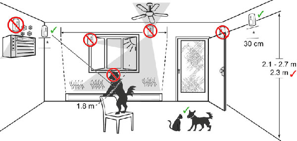
To control night lighting, choose a place from which the sensor can cover most of the room. For example, to control lighting in a hallway or stairwell, it is necessary that the motion sensor zone includes doors from all rooms or apartments. In this case, when a person enters the room from any door, the motion sensor will properly reflect and turn on the light.
For a large room, such as a large room, hall or lobby, a competent solution would be to install a ceiling sensor with 360-degree coverage and a radius that exceeds the maximum length of the room. Installation of several motion sensors in such rooms as a solution, in general, also has a place, but it is quite bulky and not convenient enough.
When installing such a control device, it is important to remember not to install it near appliances that emit infrared or electromagnetic interference, emit steam (for example kettles, etc.) or thermal radiation (heaters, heating pipes, air conditioners).
It is advisable, before the final installation of the motion detector, to test its operation in several places. This will allow you to choose the optimal place of installation with accurate triggering of the device.
Marking of the motion sensor terminals
In order to understand how to connect a motion sensor in a circuit to control lighting, you need to understand a few important aspects: what voltage this type of device works with and how the sensor terminals are labeled, to which the supply wires and the device will be connected.
Standard motion sensors are designed to work on AC 220V, but there are variants that work on 12V DC (to control LED strips) and radio sensors that are battery-powered and serve to send a signal to the control device.
The marking of terminals on the device is usually made on the body itself by means of embossing on plastic or using special stickers. The wiring diagram is also made on the case, as well as in the manual for connecting, setting up and operating this device.
Standard designations are made as follows:
- the letter L stands for the terminal to which the incoming phase is connected;
- The letter N denotes the terminal to which the neutral conductor is connected;
- L' (or another letter) denotes the outgoing phase to the lighting fixture.
In this case, unlike other electrical appliances, it is very important not to mix up the phase and zero conductors when connecting. This is because the motion sensor, like a switch, must interrupt the phase conductor, not the zero conductor (For safe operation, this requirement is stated in the ПУЭ). It is possible to determine where the phase and the zero are by color-coding the conductors (Usually brown or black is for the phase and blue is for the neutral.), but the best way to do it a screwdriver-tester or a multimeter.
Principal electrical wiring diagrams
Connecting a motion sensor into a circuit to control a lighting device in general should not cause much difficulty even for the average user who does not know much about electricity. Of course it is better to have a professional electrician do the wiring, but to save money you can familiarize yourself with the following schematic diagrams and connect everything yourself.
Two wire motion sensor connection
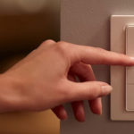
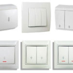
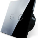
This method of connecting the motion sensor is done with two wires and involves only a phase (without using a zero). These devices are often used to mount them in standard sockets to replace common switches or to switches and motion detectors.
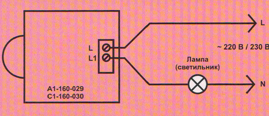
These motion detectors have only two pins: the first is used to connect the supply phase and the second for the outgoing phase conductor to the luminaire. The entire connection is done similarly to a normal single push-button switch without the use of a zero.
This method is often used when introducing motion sensors in rooms that have already been renovated, because it allows you to replace the key switches with a switch with a motion sensor.
Three-wire connection scheme
The most common wiring scheme for motion sensors is one that has a three-wire connection scheme. They are used both indoors and outdoors (when installing outdoors, it is important to pay attention to degree of dust and moisture resistance).
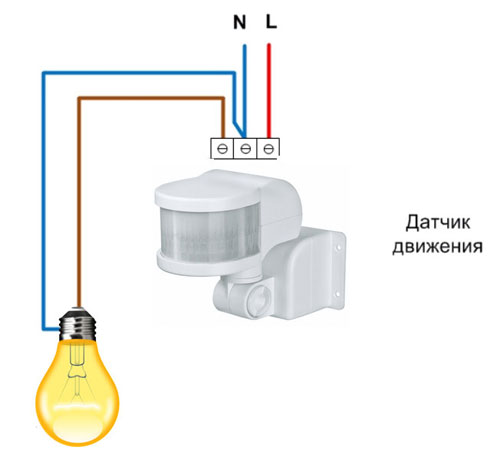
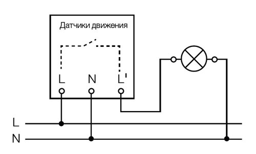
To connect three-wire sensors, it is necessary to bring phase and zero to them. The wiring diagram is as follows:
- from the junction box to the sensor bring the supplying phase and zero conductor;
- From the outgoing phase outlet of the movement detector, the conductor is led directly (or through the junction box) stretches to the lighting device.
- Also the neutral conductor is led to the lamp from the junction box.
Leading wires to the sensor are connected to pins L (phase) and N (zero), and the outgoing one to the L' terminal (or another letter, e.g. A)..
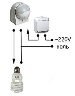
Wiring diagram for connecting the motion sensor with a switch
The universal wiring diagram of the motion detector includes its use with a standard single pushbutton. This type of connection is as follows: not only is the phase supplied to the motion detector, but also to the switch (that is, the parallel connection). The outgoing phase is led to the lighting fixture from the push-button switch as well as the outgoing phase from the movement sensor.
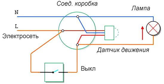
This method is very convenient for lighting control, as it allows you to turn on and off the lighting fixture, regardless of the time of day, and the serviceability and sensitivity of the motion sensor.
It is also possible to connect a switch in series with the motion sensor before it and switch off both the sensor and the lighting fixture with it. It is difficult to imagine where such a connection scheme can be used, because it has obvious disadvantages:
- If the switch is turned off, the sensor will not work and the light will not turn on automatically when motion is detected.
- If you switch the single-arm switch to the "ON" - the light may not turn on immediately, as it takes 15 to 30 seconds for the motion sensor to start in the operating mode.
Wiring diagram of multiple sensors
Several motion sensors can be connected to control the light. This method is used in large rooms or long corridors. For example, in a long hallway there is no way to control lighting with a single sensor, because it has a limited range (usually 10-12 meters), and if there are corners, it is even more difficult to turn on the light in this way. To do this in pass-through areas set a few motion sensors with installation steps equal to their radius of action. In this case, a person leaving the range of one device will certainly fall into the zone of action of another sensor and the light will not turn off.
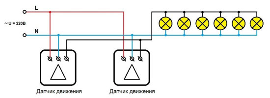
For the correct operation of lighting apply parallel connection of such devices of registration of movement, thus it does not matter their quantity in a chain.
Scheme with a starter or contactor
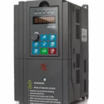
To control heavy loads, such as for controlling street lightingFor heavy loads, such as street lights with luminaires over 1kW, direct control with a motion detector is not suitable as it will burn out due to the high current flowing through it.
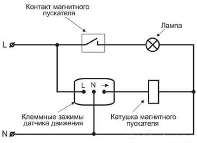
In this case a scheme with load switching by means of magnetic starter or a contactor. The control circuit will look as follows:
- the load (several high-power lighting fixtures) will be connected to the contactor or electromagnetic The contactor or electromagnetic relay of the starter;
- motion sensor will also be connected to the relay or contactor, but to the control terminals.
It will work like this: when motion is detected, the sensor supplies voltage to the starter coil, the solenoid in the starter closes the contacts and turns on the load by means of electromagnetic induction. In this case, the motion sensor and the load are galvanically isolated and are not connected to each other.
Setting and adjusting the parameters of the device
To ensure that the device responds correctly to the movement and does not react to interference, movement of pets or branches outside the window, it is important not only to install it correctly, but also to set it correctly.
View angle
Some devices allow you to control the viewing angle with a special switch on the body of the device. This makes it possible to reduce or, conversely, increase the angle of the monitored area by the motion sensor for correct triggering. Those devices that do not have adjustable viewing angle are adjusted by turning them in the desired direction or by using the wall as a limiter. Shrews also resort to the help of duct tape, artificially limiting the view of the sensor by gluing its scanning screen in the right places.
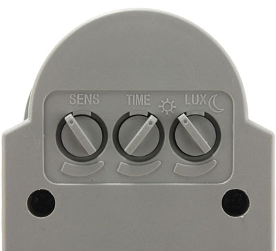
Sensitivity (SENS)
This switch allows you to reduce the number of false alarms from pets, tree branches outside the window and other factors. Adjustment according to this factor starts with the minimum value of the switch, and then increases to the desired value. All this is done experimentally with obligatory testing.
Turn off delay (TIME)
The possibility of setting a delay depends on the particular device and can be in the range from 5 seconds to 30 minutes. The setting for this parameter is made based on the user's preference and the purpose of the room or lighting. It works as follows: when motion is detected, the lights turn on and then turn off only after the set delay on the device has elapsed.
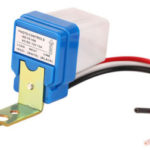
Light level (LUX/DAY LIGHT)
This setting is used to regulate the switching on of the illuminator at a given brightness level. That is, it will only turn on if motion detection occurs at the set brightness level. If the illumination in the room is higher, the device will not turn on. Adjustment is performed from the minimum value, gradually increasing to the required value.
Mounting and connection mistakes
The main mistakes when installing the motion detector are wrong choice of installation place and setting its parameters (sensitivity, illuminance). In this situation, the sensor may not work when a person is in the room, turn on with a delay or when pets move. Therefore, the setting itself takes a long time and must take into account all the conditions in which the device will work.
The wiring itself is usually not difficult - to connect the three wires according to the scheme is quite simple. The main thing here is not to mix up the phase and zero, and connect conductors that do not have violations of insulation and damage to the veins.
Related articles: