When designing electronic circuits, it is often necessary to compare the level of two voltages. For this purpose, such a device as a comparator is used. The name of the node goes back to the Latin comparare, or rather to the English to compare.
Contents
What is a voltage comparator
Generally speaking, a comparator is a device with two inputs for the values (voltages) being compared and an output for the result of the comparison. The comparator has two inputs for feeding the compared parameters - direct and inverse. The output is set to logical one if the voltage of the direct input exceeds the voltage of the inverse input and zero if vice versa. If a positive difference between the inversion input and the direct input equals one, and a zero in the opposite situation, the comparator is called an inverting comparator.
Comparator operating principle
It is convenient to build a comparator using operational amplifier (OP-AMP). For this purpose its properties are directly used:
- amplification of the signal difference between the direct and inverting inputs;
- infinite (in practice - from 10000 and higher) gain.
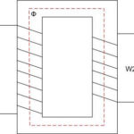
The work of DT as a comparator can be considered with the following circuit:
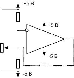
Suppose there is a DT with a gain of 10000, the supply voltage is bipolar, + 5 V and minus 5 V. The divider is set to a reference level of exactly 0 volts at the inverting input, and minus 5 volts is taken from the potentiometer slider at the direct input. Operational amplifier should amplify the difference by 10000 times, theoretically on the output there should be a voltage of minus 50000 volts. But there is nowhere for the op-amp to get such voltage, so it creates the maximum possible - supply voltage, minus 5 volts.
If you start to raise the voltage at the direct input, Op-Amp will try to set the voltage difference between the inputs multiplied by 10000. It will succeed when the input voltage approaches zero and becomes about minus 0.0005V. With further increase in the input voltage at the positive input, the output voltage will rise to zero or higher, and at +0.0005 volts will become equal to +5 V and will not rise further - there is nowhere. Thus, when the input voltage passes the zero level (more precisely, minus 0.0005 volts to +0.0005 volts) there will be a jump in the output voltage from minus 5 volts to +5 volts. In other words, as long as the voltage at the direct input is lower than at the inverting input, zero is set at the comparator output. If higher, it is one.
Of interest is the section of level difference at the inputs from minus 0.0005 volts to + 0.0005 volts. In theory, it will have a smooth rise from negative to positive supply voltage. In practice, this range is very narrow, and due to noise, interference, supply voltage instability, etc. when the voltages at the inputs are approximately equal, there will be chaotic triggering of the comparator in both directions. The lower the gain of the Op-Amp, the wider this window of instability is. If the comparator controls the actuator, it will cause it to operate in tact (relay clicking, valve slamming, etc.), which may lead to its mechanical failure or overheating.
To avoid this, a shallow positive feedback is created by turning on the resistor indicated by the dashed line. This creates a small amount of hysteresis by shifting the switching thresholds when the voltage goes up and down relative to the reference. For example, up the comparator will switch at 0.1 volts and down at exactly zero (depending on the depth of feedback). This would eliminate the instability window. The rating of this resistor can be from a few hundred kilohms to a few megaohms. The lower the resistance, the greater the difference between the thresholds.
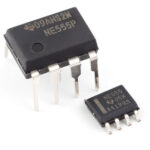
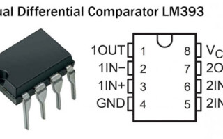
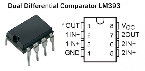
Specialized comparator chips are also available. For example the LM393. These chips have a fast operational amplifier (or several) and may have a built-in divider that creates a reference voltage. Another difference between these comparators and devices built on Op-Amps is that many of them require a single-ended power supply. Most opacitors need a bi-polar voltage. The choice of chip type is determined by the design of the device.
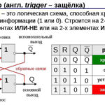
Features of Digital Comparators
Comparators are also used in digital technology, although it sounds paradoxical at first glance. After all, there are only two voltage levels - one and zero. It makes no sense to compare them. But you can compare two binary numbers, into which you can also convert any analog values (including voltage).
Suppose there are two binary words of equal length in bits:
X=X3X2X1X0 and Y=Y3Y2Y1Y.
They are considered equal in value if all bits are bitwise equal:
1101=1101 => X=Y.
If at least one bit is different, then the numbers are unequal. The greater number is determined by a bit by bit comparison, starting from the highest bit:
- 1101>101 - here the first bit of X is greater than the first bit of Y, and X>Y;
- 1101>101 - the first bits are equal, but the second bit of X is bigger and X>Y;
- 111<1110 - Y has a bigger third bit and the bigger value in the lower bit of X does not matter, X
The implementation of such a comparison can be built on I-NE, OR-NE base element logic circuits, but it is easier to use off-the-shelf products. For example, 4063 (CMOS), 7485 (TTL), domestic K564IP2 and other series of microcircuits. They are 2-8 bit comparators with a corresponding number of data inputs and control inputs. The outputs of digital comparators are in most cases 3:
- more;
- less than;
- equal.
Unlike analog devices, equality on inputs in binary comparators is not an undesirable situation and they do not try to avoid it.
Such device can be easily built using Boolean algebra functions. Alternatively, many microcontrollers have on-board analog comparators with separate external pins, which give to internal circuit a ready-made result of comparing two values as 0 or 1. This saves resources of small computer systems.
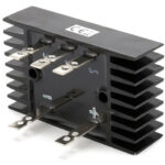
Where a voltage comparator is used
The comparator is used in a wide range of applications. For example, it can be used to build a threshold relay. This requires a sensor that converts any value into voltage. Such a value can be:
- level of illumination;
- noise level;
- liquid level in the vessel or tank;
- any other values.
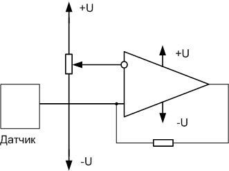
The potentiometer can be used to set the response level of the comparator. The output signal is given through a key to the indicator or actuator.
If the hysteresis is increased, the comparator can act as a Schmitt trigger. When a slowly varying voltage is applied to the input, the output is discrete signal with steep edges.
The two elements can be connected in a dual-threshold comparator, or window comparator.
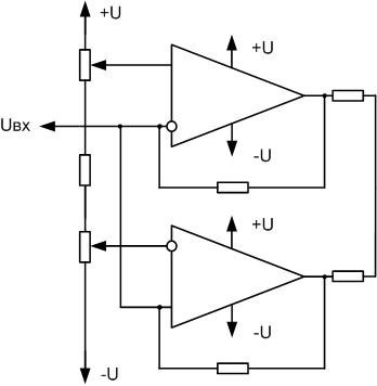
Here, the threshold voltage is set separately for each comparator - for the upper one on the direct input, for the lower one on the inverse input. The free inputs are combined and the measured voltage is applied to them. The outputs are connected according to the "mounting OR" circuit. When the voltage exceeds the set upper or lower limit, one of the comparators gives a high level at the output.
A multi-level comparator is assembled from several elements, which can be used as a linear voltage indicator, or a value that is converted to voltage. For four levels the circuit will be like this:
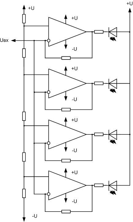
In this circuit, each element has a different reference voltage applied to its input. The inverting inputs are connected together and the signal to be measured comes to them. When the triggering level is reached, the corresponding LED lights up. If the emitting elements are arranged in a line, you get a light bar, the length of which varies according to the level of the applied voltage.
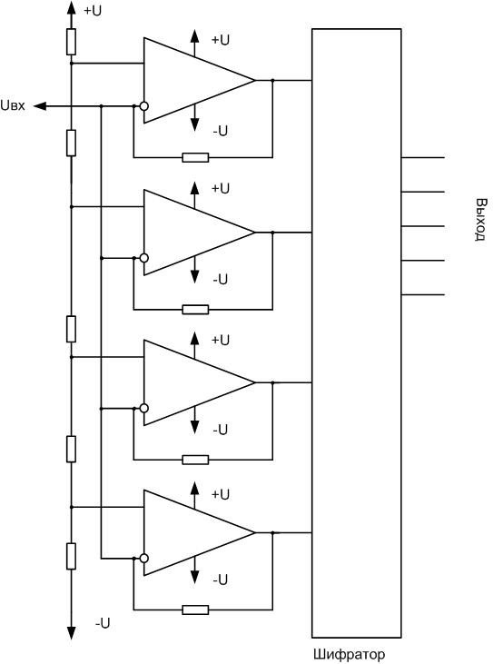
The same circuit can be used as an analog-to-digital converter (ADC). It converts the input voltage into a corresponding binary code. The more elements are included in the ADC, the higher the digit capacity, the more accurate the conversion. In practice, the line code is inconvenient to use, and it is converted into the usual code with the help of an encoder. Encoder can be built on logic elements, use ready-made microcircuit or use ROM with appropriate firmware.
The sphere of application of comparators in professional and amateurish circuitry is wide. Competent application of these elements allows to solve a wide range of tasks.
Related articles: