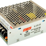
AC voltage is delivered from the power supply company to the consumers. This is due to the peculiarities of transporting electricity. But most of the household (and, partially, industrial) electrical consumers require direct voltage supply. To obtain it, converters are required. In many cases they are built according to the "step-down transformer - rectifier - smoothing filter" scheme (except for switching power supplies). Diodes in a bridge circuit are used as rectifiers.
Contents
What diode bridge is diode bridge for and how it works
Diode bridge is used as a rectification circuit that converts alternating voltage to direct voltage. It operates based on one-way conduction, a property of a semiconductor diode to pass current only in one direction. A single diode can also serve as the simplest rectifier.
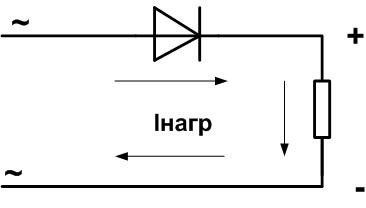
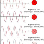
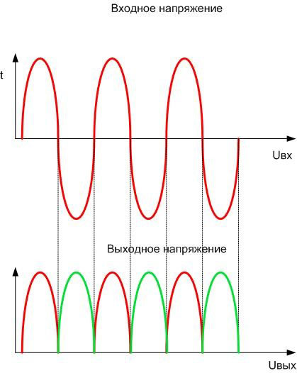
With this type of connection, the diode at the bottom (negativepart of the sine wave is "cut off". This method has disadvantages:
- the shape of the output voltage is far from constant, a large and cumbersome capacitor is required as a smoothing filter;
- the AC power supply is used at most half of its capacity.

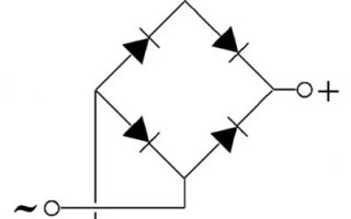
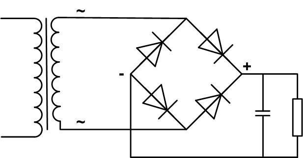
The current through the load repeats the shape of the output voltage. Therefore, it is better to use a double half-period rectifier in the form of a diode bridge. If you include four diodes in the above circuit and connect the load, then the unit will work as follows when the AC voltage is applied to the input:
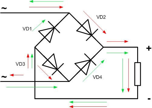
When the voltage is positive (upper part of the sine wave, red arrow), the current will go through diode VD2, load, VD3. With negative voltage (lower part of the sinusoid, green arrow) through diode VD4, load, VD1. As a result, in one period the current passes through the load twice in the same direction.
The shape of the output voltage is much closer to a straight line, although the level of ripple is quite high. The power of the source is fully used.
If there is a source of three-phase voltage of the required amplitude, you can make a bridge according to this scheme:
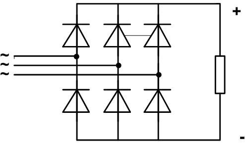
It will stack three currents on the load, repeating the shape of the output voltage, with a phase shift of 120 degrees:
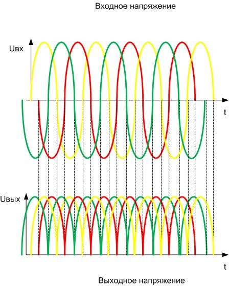
The output voltage will circle the tops of the sinusoids. You can see that the voltage pulses much less than in the single-phase circuit, its shape is closer to a straight line. In this case, the capacitance of the smoothing filter will be minimal.
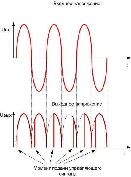
And another variant of the bridge is a controlled bridge. In it, the two diodes are replaced by thyristors - electronic devices that open when a signal is applied to the control electrode. When open, thyristors behave almost like regular diodes. The circuit takes this form:
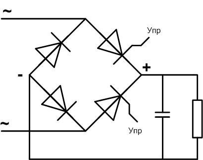
Switching signals are applied from the control circuit at the agreed moments of time, switching off takes place at the moment of voltage transition through zero. Then the voltage is averaged over a capacitor and this average can be controlled.
Diode bridge designation and connection diagram
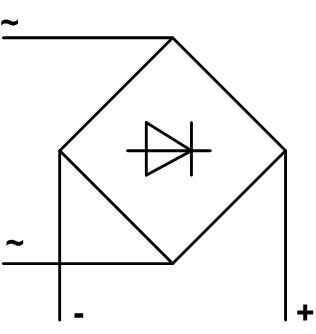
Since a diode bridge can be built according to various schemes and contains few elements, in most cases the rectifier unit is identified simply by drawing a schematic diagram. If this is unacceptable - for example, in the case of a block diagram - then the bridge is indicated in the form of a symbol, which indicates any converter of AC voltage into DC:
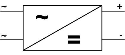
The letter "~" stands for circuits AC circuitsThe symbol "~" stands for AC circuits, "=" for DC circuits, and "+" and "-" for the output polarity.
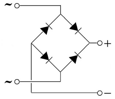
If the rectifier is built according to the classic bridge circuit of 4 diodes, a slightly simplified representation is allowed:
The input of the rectifier unit is connected to the output terminals of the AC source (in most cases it is a step-down transformer) without observing polarity - any output terminal is connected to any input terminal. The output of the bridge is connected to the load. It may or may not require polarity (including stabilizer, smoothing filter).
The diode bridge may be connected to a constant voltage source. In this case we have a protection circuit against unintentional reverse polarity - any connection of the bridge inputs to the power supply output will not change the polarity of the voltage at its output.
Basic Specifications
When choosing diodes or a bridge, you should first of all look at Highest operating forward current. It should exceed the load current with a margin. If this value is unknown and the power is known, it must be recalculated to the current according to the formula Inagr=Pnagr/Uf. To increase the allowable current, the semiconductors can be connected in parallel - the highest load current is divided by the number of diodes. Diodes in one branch of the bridge in this case it is better to choose by close value of voltage drop in the open state.
The second important parameter is forward voltageThe second important parameter is the forward voltage, for which the bridge or its elements are designed. It must not be lower than the AC source output voltage (amplitude value!). For reliable operation of the device you should take a margin of 20-30%. To increase the allowable voltage, diodes can be included in series - in each shoulder of the bridge.
These two parameters are enough for a preliminary decision on the use of diodes in the rectifier device, but you should pay attention to some other characteristics:
- maximum operating frequency - usually a few kilohertz and for operation at industrial frequencies of 50 or 100 Hz does not matter, but if the diode will operate in a pulse circuit, this parameter can become decisive;
- The open state voltage drop of silicon diodes is about 0.6 V, which is not important for output voltage, for example, of 36 V, but can be critical when operating below 5 V - in this case, we should choose Schottky diodes, which are characterized by a low value of this parameter.
Types of diode bridges and their marking
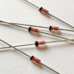
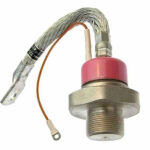
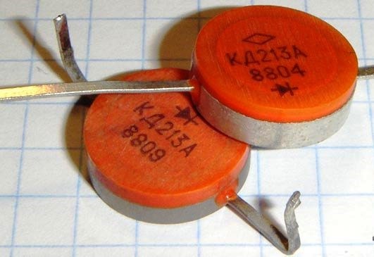
Diode bridge can be assembled on discrete diodes. To observe the polarity, you need to pay attention to the markings. In some cases, the label in the form of a drawing is applied directly to the body of the semiconductor device. This is typical for domestically made products.
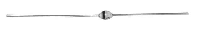
Foreign (and many modern Russian) devices are marked with a dot or a ring. In most cases, the anode is marked in this way, but there is no guarantee. It is better to look in a reference book or use a tester.
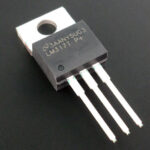
You can make a bridge from an assembly - four diodes are combined in one case, and the connection of the terminals can be made by external conductors (for example, on a printed circuit board). Assemblies can be different, so you have to look at the datasheets for the correct connection.
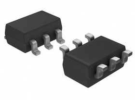
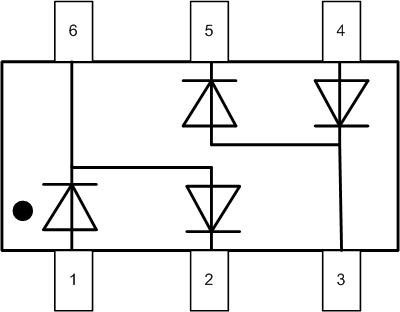
For example a diode assembly BAV99S with 4 diodes but only 6 pins has two half-bridges connected inside (there is a dot on the case near pin 1):
To get a full bridge, you have to connect the corresponding pins with external conductors (red shows the track layout when using printed circuit wiring):
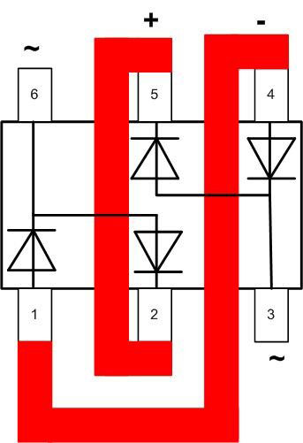
In this case the AC voltage is brought to pins 3 and 6. The positive pole of the DC is taken from pin 5 or 2 and the negative pole from pin 4 or 1.
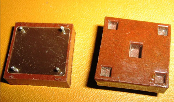
And the simplest option is an assembly with a ready-made bridge inside. Among domestic products it can be КЦ402, КЦ405, there are bridges assemblies of foreign production. The marking of terminals in many cases is applied directly on the case, and the problem comes down only to the correct choice according to the characteristics and to error-free connection. If there is no external pin designation, you will have to refer to a reference book.
Advantages and disadvantages
The advantages of a diode bridge are well known:
- decades of proven circuitry;
- Easy to assemble and connect;
- easy fault diagnosis and easy repair.
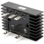
As disadvantages we should mention the growth of dimensions and weight of the circuit with increasing power, as well as the need to use heat sinks for high-power diodes. But nothing can be done about it - you can't cheat physics. When these conditions become unacceptable, it is necessary to decide on the transition to the switching power supply circuit. By the way, the bridge connection of diodes can be used in it as well.
We should also note the shape of the output voltage, which is far from constant. To work with consumers with requirements to supply voltage stability, it is necessary to use the bridge together with smoothing filters and, if necessary, stabilizers at the output.
Related articles: