Semiconductor diode has many "professions". It can rectify voltage, decouple electric circuits, protect equipment from improper power supply. But there is a not-so-normal kind of diode "operation" when its one-way conduction property is used very indirectly. A semiconductor device for which the normal mode of operation is reverse bias is called a stabilizing diode.
Contents
What is a zener diode, where it is used and what kinds exist
A stabilitron, or Zener diode (named after the American scientist who first studied and described the properties of this semiconductor device), is a regular diode with a p-n junction. Its peculiarity is its operation on the negative bias portion of the characteristic, i.e., when the voltage is applied in reverse polarity. Such a diode is used as an independent stabilizer, maintaining the consumer voltage constant regardless of load current variations and input voltage fluctuations. Also nodes on stabilitrons are used as reference voltage sources for other stabilizers with advanced circuitry. Less frequently, the reverse diode is used as a pulse shaping element or a surge suppressor.
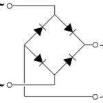
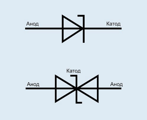
There are conventional stabilitrons and two-canon diodes. A two-carbon stabilitron is two diodes in opposite directions in the same case. It can be replaced with two separate devices by connecting them according to a suitable circuit.
Volt-ampere Characteristics of a Stabilitron and How It Works
To understand how a Stabilizer works, you have to study its typical volt-ampere characteristic (VAC).
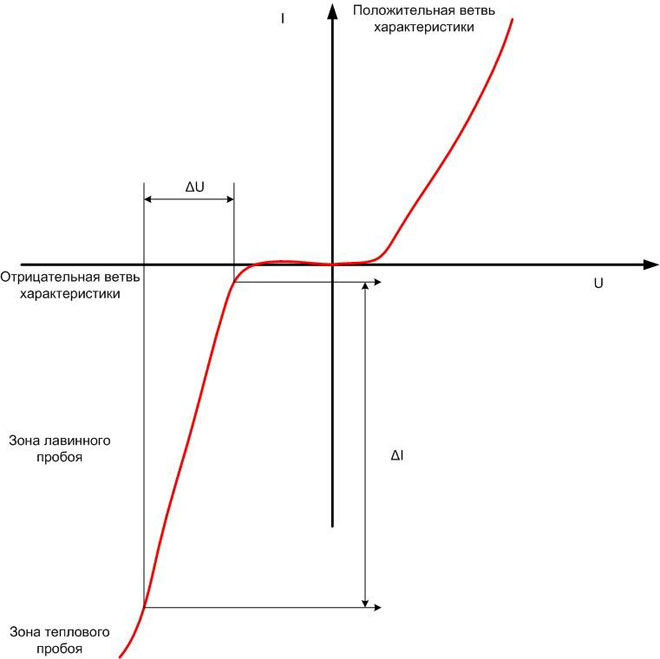
If you apply voltage to the zener in the forward direction, as a normal diode, it will behave like a normal diode. At a voltage of about 0.6 V (for a silicon device) it will open and go to the linear section of the CVC. On the topic of the article, it is more interesting to see how a stabilizing diode behaves when a voltage of the opposite polarity is applied (the negative side of the characteristic). At first its resistance will increase sharply and the device will stop carrying current. But when the voltage reaches a certain value, there will be a sharp increase in current, called breakdown. It is avalanche-like, and disappears when the power is removed. If the reverse voltage continues to increase, the p-n junction will begin to heat up and go into thermal breakdown mode. Thermal breakdown is irreversible and means that the diode will fail, so you should not put the diode in this mode.
The operation section of the semiconductor device in the avalanche breakdown mode is interesting. Its shape is close to linear, and it has a high steepness. This means that with a large change in current (ΔI) the change in voltage drop across the stabilizer is relatively small (ΔU). And this is stabilization.
This behavior when the reverse voltage is applied is characteristic of any diode. But the peculiarity of the stabilizing diode is that its parameters at this section of the CVC are normalized. Its stabilization voltage and the slope of the characteristic are given (with a certain spread) and are important parameters that determine the suitability of the device to be used in a circuit. These can be found in reference books. Ordinary diodes can also be used as stabilizing diodes - if you take a picture of their SVC and you find one with a suitable characteristic among them. But this is a long, time consuming process with a non-guaranteed result.
The main characteristics of a stabilizing diode are
To select a Zener diode for your application, you need to know a few important parameters. These characteristics will determine the suitability of the selected device for the task at hand.
Rated Stabilizing Voltage
The first zener parameter to look at when choosing is the stabilization voltage, which is determined by the avalanche breakdown initiation point. It is the starting point for selecting a device for use in a circuit. Different copies of ordinary zener, even of the same type, have a voltage variation in the region of a few percent, while the difference is lower for precision ones. If the nominal voltage is unknown, it can be determined by assembling a simple circuit. It is necessary to prepare:
- A ballast resistor of 1...3 kOhm;
- an adjustable voltage source;
- A voltmeter (you can use a tester).
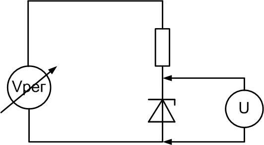
It is necessary to raise the voltage of the power supply from zero, controlling the increase of voltage on the stabilizer with a voltmeter. At some point it will stop, despite a further increase in the input voltage. This is the actual stabilization voltage. If there is no regulated source, you can use a power supply with a constant output voltage known to be higher than the U of stabilization. The circuit and measuring principle remains the same. But there is a risk of semiconductor device failure due to excessive operating current.
Stabilitrons are used for voltages from 2...3 V to 200 V. To form stable voltage below this range, other devices are used - stabilitrons, working on the straight section of the CVC.
Operating current range
The range of currents at which stabilizing diodes perform their function is limited at the top and bottom. At the bottom it is limited to the beginning of the linear segment of the inverse branch of the characteristic curve. At lower currents, the characteristic does not provide voltage constancy.
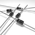
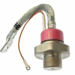
The upper value is limited by the maximum power dissipation that the semiconductor device is capable of and depends on its design. Stabilitrons in a metal case are designed for a higher current, but you must not forget about the use of heat sinks. Without them, the highest allowable power dissipation will be significantly lower.
Differential Impedance
Another parameter that determines the performance of a regulator is the differential resistance Rc. It is defined as the ratio of the change in voltage ΔU to the resulting change in current ΔI. This value has the dimension of resistance and is measured in ohms. Graphically, it is the tangent of the slope of the working section of the characteristic. Obviously, the smaller the resistance, the better the quality of stabilization. For an ideal (not existing in practice) stabilizer Rst is zero - any increase in current will not cause any change in voltage, and the section of the curve will be parallel to the axis of ordinates.
Stabilizer marking
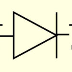
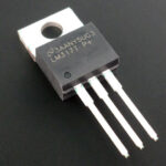
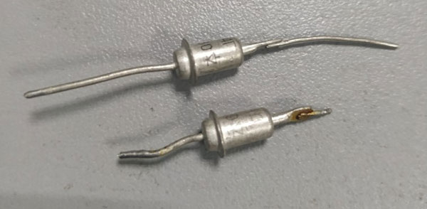
Domestic and imported metal-encapsulated stabilizing diodes are labeled simply and clearly. They are marked with the name of the device and the location of the anode and cathode in the form of a schematic designation.
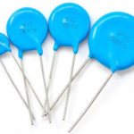
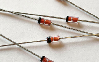
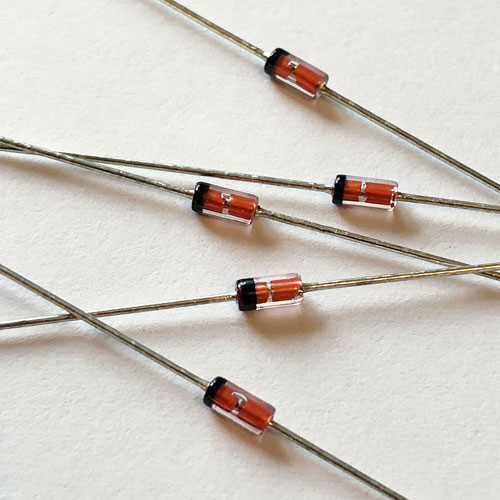
Devices in a plastic package are marked with rings and dots of different colors on the cathode and anode sides. By the color and combination of signs you can determine the type of device, but you have to look in reference books or use calculator programs. Both can be found on the Internet.
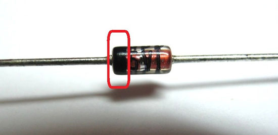
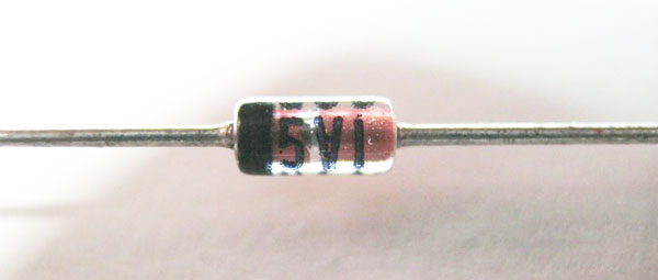
Stabilizing voltages are sometimes printed on low-power stabilizing diodes.
Switching Diagrams for Stabilizing Diodes
The basic circuit for a Stabilizer is in series with a resistorwhich sets the current through the semiconductor device and takes the excess voltage. The two elements make up common divider. When the input voltage changes, the drop across the stabilizer remains constant and the resistor changes.
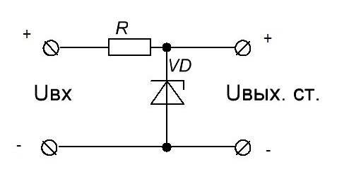
Such a circuit can be used independently and is called a parametric regulator. It keeps the load voltage constant despite fluctuations in input voltage or current consumption (within certain limits). Such a unit is also used as an auxiliary circuit where a reference voltage source is required.
It is also used to protect sensitive equipment (sensors, etc.) from abnormal high voltages (DC or random pulses) in the supply or measurement line. Anything above the semiconductor device's stabilization voltage is "cut off". Such a circuit is called a "Zener barrier."
In the past, the property of a stabilizer to "cut off" voltage tops was widely used in pulse shaping circuits. Two-channel devices were used in AC circuits.
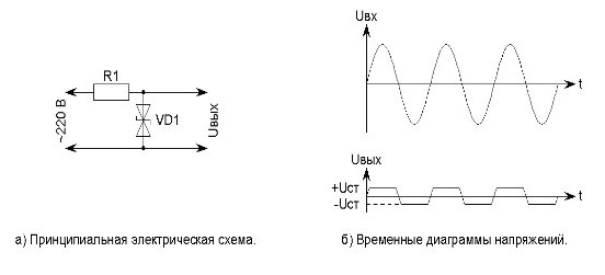
But with the development of transistor technology and the advent of integrated circuits this principle has rarely been used.
If you don't have a regulator for the voltage you want, you can make one of two. The total stabilization voltage will be equal to the sum of the two voltages.
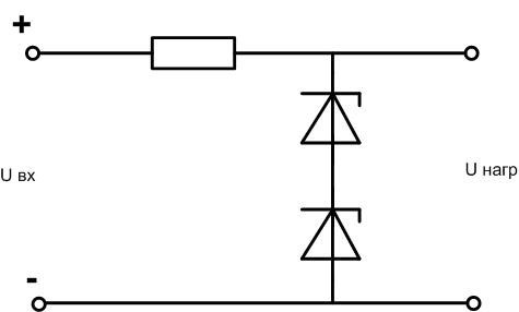
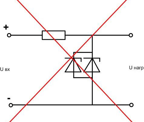
Important! Stabilitrons must not be connected in parallel to increase the operating current! The difference in volt-ampere characteristics will lead to the output in the zone of thermal breakdown of one stabilitron, then will fail the second one because of excess of load current.
Although the technical documentation from Soviet times allows parallel the parallel connection of zener in parallel, but with the proviso that the devices must be of the same type and the total actual power dissipation during operation should not exceed the allowable for a single stabilitron. That is, an increase in operating current under such a condition cannot be achieved.
To increase the permissible load current another scheme is used. The parametric stabilizer is complemented by a transistor, and we get an emitter repeater with a load in the emitter circuit and a stable voltage on the transistor base.
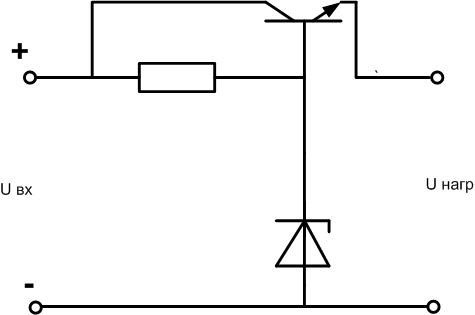
In this case output voltage of stabilizer will be less than U-stabilization by the value of voltage drop at emitter junction - for silicon transistor about 0,6 V. To compensate for this reduction, a diode can be connected in series with the stabilizer in the forward direction.
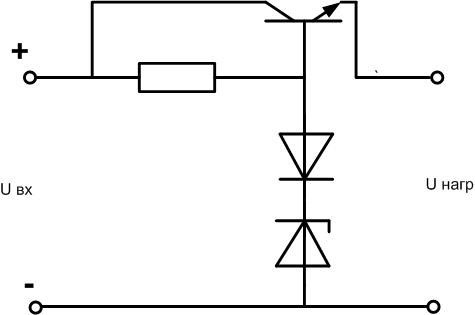
In this way (by including one or more diodes) you can adjust the output voltage of the regulator upwards within small limits. If it is necessary to drastically increase the Uv, it is better to include one more diode in series.
The scope of application of the stabilitron in electronic circuits is vast. With a conscious approach to the choice this semiconductor device will help to solve many tasks set for the developer.
Related articles: