Budget option to convert the main parameters of the electric current are voltage dividers. Such a device is easy to make yourself, but to do this, you need to know the purpose, cases of application, the principle of operation and examples of calculations.
Contents
Designation and application
A transformer is used to convert alternating voltages, so that a sufficiently high current value can be maintained. If a load with a small current (up to hundreds of mA) is to be added to the circuit, a transformer voltage (U) converter is not advisable.
In these cases, you can use a simple voltage divider (DN), the cost of which is significantly lower. After obtaining the necessary value of U is rectified and power is supplied to the consumer. If necessary, to increase the current (I), an output power increase stage should be used. In addition, there are also constant U dividers, but these models are used less often than others.
DNs are often used for charging various devices, in which it is necessary to obtain from 220 V lower U values and currents for different types of batteries. In addition, it is reasonable to use devices for dividing U for creating electric measuring instruments, computer equipment, as well as laboratory pulse and ordinary power supplies.
Principle of operation
A voltage divider (DN) is a device in which the relationship between the output and input U through the transfer coefficient. The transfer coefficient is the ratio of U values at the output and input of the divider. The circuit of the voltage divider is simple and is a chain of two consumers connected in series - radio elements (resistors, capacitors or inductors). They have different output characteristics.
AC current has the following main quantities: voltage, amperage, resistance, inductance (L) and capacitance (C). Formulas for calculating the basic values of electricity (U, I, R, C, L) when consumers are connected in series:
- Resistance values add up;
- Voltages are added;
- Current will be calculated according to Ohm's law for the circuit section: I = U / R;
- The inductances are added;
- The capacitance of the whole chain of capacitors: C = (C1 * C2 * ... * Cn) / (C1 + C2 + ... + Cn).
To make a simple resistor DN and the principle of series connected resistors is used. Conditionally the circuit can be divided into 2 shoulders. The first arm is the upper one and is between the input and the zero point of the DN, and the second arm is the lower one, from which the output U is taken.
The sum of U on these shoulders is equal to the resultant value of the input U. DNs are of linear and nonlinear types. Linear devices are those with an output U, which varies linearly with the input value. They are used to set the desired U in different parts of circuits. Non-linear are used in functional potentiometers. Their resistance can be active, reactive and capacitive.
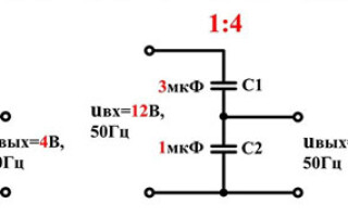
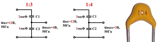
In addition, a DN can also be capacitive. It uses a chain of 2 capacitors that are connected in series.
Its principle of operation is based on the reactive component of the resistance of the capacitors in a circuit with a variable component. The capacitor has not only capacitive characteristics, but also a resistance Xc. This resistance is called capacitive resistance, depends on the frequency of the current and is determined by the formula: Xc = (1 / C) * w = w / C, where w is the cyclic frequency, C is the capacitor value.
The cyclic frequency is calculated by the formula: w = 2 * PI * f, where PI = 3.1416, and f is the AC frequency.
The capacitor, or capacitive, type allows relatively higher currents than from resistive devices. It is widely used in high-voltage circuits where the U-value needs to be reduced several times. In addition, it has the significant advantage of not overheating.
The inductive type of DN is based on the principle of electromagnetic induction in circuits with a variable component. The current flows through a solenoid, the resistance of which depends on L and is called inductive. Its value is directly proportional to the frequency of the alternating current: Xl = w * L, where L is the inductance value of the circuit or coil.
The inductive DN only works in circuits with a current that has a variable component and has an inductive resistance (Xl).
Advantages and disadvantages
The main disadvantages of the resistive DN are that it cannot be used in high frequency circuits, the significant voltage drop across the resistors and the reduction in power. In some circuits it is necessary to select the power of resistors, because there is a significant heating.
In most cases in AC circuits, active load (resistive) DNs are used, but with compensation capacitors connected in parallel to each of the resistors. This approach reduces heating, but does not remove the main disadvantage, which is the loss of power. The advantage is the use in DC circuits.
To eliminate the power loss on the resistive DN, the active elements (resistors) should be replaced by capacitive elements. Capacitive element in relation to the resistive DN has several advantages:
- It is used in AC circuits;
- There is no overheating;
- Power loss is reduced because the capacitor has no power, unlike a resistor;
- Can be used in high-voltage power supplies;
- High efficiency (coefficient of performance);
- Lower I-loss.
The disadvantage is that it cannot be used in circuits with constant U. This is due to the fact that the capacitor in DC circuits does not have capacitance, but only acts as a capacitor.
An inductive DN in AC circuits also has a number of advantages, but it can also be used in constant U circuits. An inductor coil has a resistance, but because of the inductance, this option is not suitable because there is a significant drop in U. Main advantages over the resistive type of DN:
- Application in networks with variable U;
- Heating of components is negligible;
- Less power loss in AC circuits;
- Comparatively high efficiency (higher than capacitive);
- Use in high-precision measuring equipment;
- Lower inaccuracy;
- Load connected to divider output has no effect on division ratio;
- Current losses are less than capacitive dividers.
The disadvantages are as follows:
- The use of constant U in the power supply networks leads to significant current losses. In addition, the voltage drops sharply due to the consumption of electrical energy for inductance.
- The output signal by frequency characteristics (without the use of a rectifier bridge and filter) varies.
- Not applicable in high voltage AC circuits.
Calculation of a voltage divider with resistors, capacitors, and inductors
After selecting the type of voltage divider to calculate you need to use the formulas. Incorrect calculations can burn out the device itself, the current amplifying output stage, and the consumer. The consequences of incorrect calculations can be worse than the failure of radio components: fire as a result of a short circuit, as well as electrocution.
When calculating and assembling the circuit, you must clearly observe safety rules, check the device before turning it on for proper assembly and not test it in a damp room (the possibility of electrocution increases). The basic law used in calculations is Ohm's law for a circuit section. Its formulation is as follows: the current is directly proportional to the voltage in a circuit section and inversely proportional to the resistance of that section. The entry in the form of a formula is as follows: I = U / R.
Algorithm for calculating a voltage divider with resistors:
- Total voltage: Upit = U1 + U2, where U1 and U2 are the U values on each of the resistors.
- Voltages on the resistors: U1 = I * R1 and U2 = I * R2.
- Upit = I * (R1 + R2).
- No load current: I = U / (R1 + R2).
- The U drop on each of the resistors: U1 = (R1 / (R1 + R2)) * Upit and U2 = (R2 / (R1 + R2)) * Upit.
The values of R1 and R2 must be 2 times less than the load resistance.
To calculate the voltage divider on the capacitors you can use the formulas: U1 = (C1 / (C1 + C2)) * Upit and U2 = (C2 / (C1 + C2)) * Upit.
Similar formulas for calculating the DN at inductances: U1 = (L1 / (L1 + L2)) * Upit and U2 = (L2 / (L1 + L2)) * Upit.
The dividers are used in most cases with a diode bridge and a stabilitron. A stabilitron is a semiconductor device that acts as a U stabilizer. Diodes should be chosen with reverse U above the allowable U in this circuit. The stabilitron should be chosen according to the reference book for the required value of the stabilizing voltage. In addition, a resistor should be included in the circuit before it, because without it the semiconductor device will burn out.
Related articles: