Electrical energy is conveniently transported and converted by magnitude in the form of alternating voltage. It is in this form it is delivered to the end user. But to power many devices you still need direct voltage.
Contents
Rectifiers in electrical engineering
Rectifiers are tasked with converting alternating voltage to direct voltage. This device is widely used, and the main uses of rectifier devices in radio and electrical engineering:
- Formation of direct current for power electrical installations (traction substations, electrolysis plants, excitation systems of synchronous generators) and powerful direct current motors;
- power supplies for electronic devices;
- detection of modulated radio signals;
- Formation of direct voltage, proportional to input signal level, for building automatic gain control systems.
The full scope of rectifier applications is vast, and it is impossible to list them all in one overview.
Principles of Rectifiers
Rectifier devices are based on the property of one-way conduction of the elements. This can be done in different ways. Many ways for industrial applications are a thing of the past, such as using mechanical synchronous machines or vacuum devices. Nowadays, valves that conduct current to one side are used. Not so long ago, mercury devices were used for high-power rectifiers. Nowadays, these have been practically superseded by semiconductor (silicon) elements.
A typical rectifier circuit
Rectifier device can be built according to different principles. When analyzing schemes of devices, it should be remembered that voltage at the output of any rectifier can be called constant only conditionally. This unit produces a pulsating unidirectional voltage, which in most cases must be smoothed by filters. Some consumers also require stabilization of the rectified voltage.
Single phase rectifiers
The simplest AC voltage rectifier is a single diode.
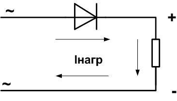
It passes the positive half-wave of the sine wave to the consumer and "cuts off" the negative half-wave.
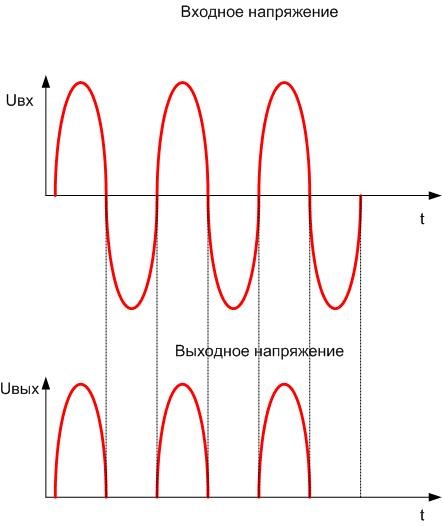
The field of application of such a device is small - mainly, Rectifiers in switching power suppliesThe rectifiers of switched-mode power supplies operating at relatively high frequencies. Although it delivers current flowing in one direction, it has significant disadvantages:
- high level of ripple - a large and cumbersome capacitor will be required to smooth out and obtain a constant current;
- incomplete use of power of step-down (or step-up) transformer, leading to an increase in the required weight and dimensions;
- average output EMF is less than half of the input EMF;
- increased requirements for the diode (on the other hand - only one valve is needed).
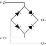
Therefore, the most widespread is Two half-period (bridge) circuit.
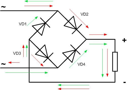
Here, the current through the load flows twice per period in the same direction:
- the positive half-wave along the path indicated by the red arrows;
- the negative half-wave along the path indicated by the green arrows.
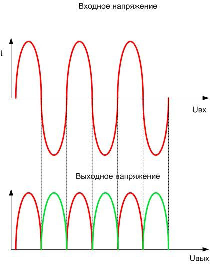
The negative wave is not lost and is also used, so the power of the input transformer is used more fully. The average EMF is twice that of the single half-wave version. The shape of the pulsating current is much closer to a straight line, but a smoothing capacitor is still needed. Its capacity and dimensions will be smaller than in the previous case, because the frequency of pulsation is twice the frequency of the mains voltage.
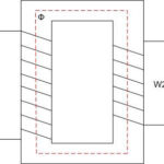
If you have a transformer with two identical windings, which can be connected in series or with a winding that has a tap off the middle, a double-half-period rectifier can be built according to another circuit.
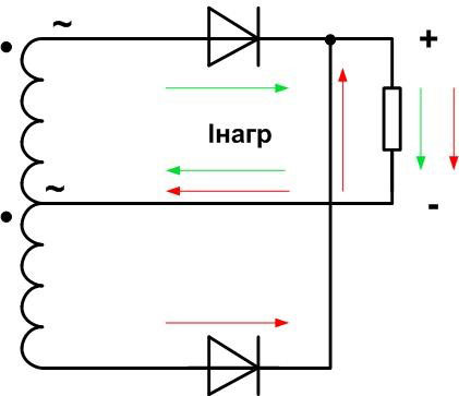
This is actually a doubling of the single half-period rectifier, but has all the advantages of the double half-period. The disadvantage is the need for a transformer of specific design.
If the transformer is made as an amateur, there is no obstacle to winding the secondary as required, but the iron will have to be somewhat oversized. But instead of 4 diodes only 2 diodes are used. This will compensate for the loss in weight and dimensions, and even win.
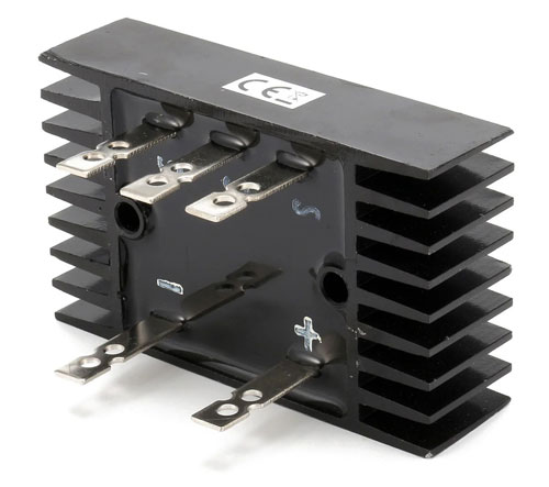
If the rectifier is designed for high current and the valves have to be mounted on heat sinks, then installing half the number of diodes gives significant savings. You should also take into account that such rectifier has twice the internal resistance compared to the bridge circuit, so the heating of the transformer windings and the associated losses will also be higher.
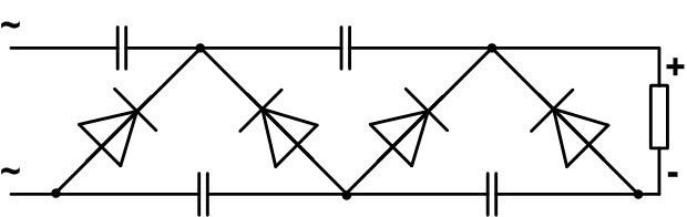
Three-phase rectifiers
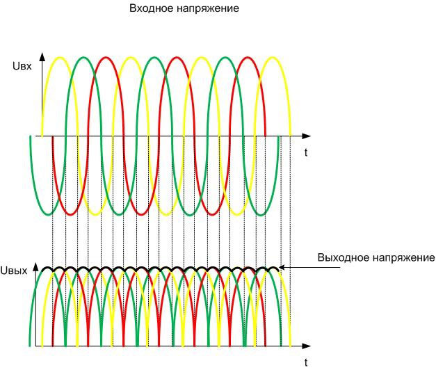
From the previous circuit, it is logical to move on to a three-phase voltage rectifier assembled on a similar principle.
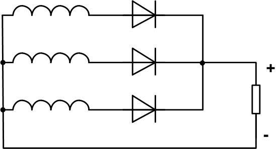
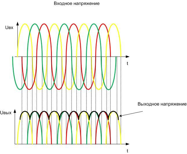
The shape of the output voltage is much closer to a straight line, the level of ripple is only 14%, and the frequency is equal to triple the frequency of the mains voltage.
And yet the source of this circuit is a single half-period rectifier, so many disadvantages cannot be eliminated even with a three-phase voltage source. The main one is that the transformer power is not fully utilized, and the average EMF is 1.17⋅E2eff (effective transformer secondary EMF).
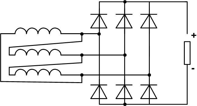
The best parameters have the bridge three-phase circuit.
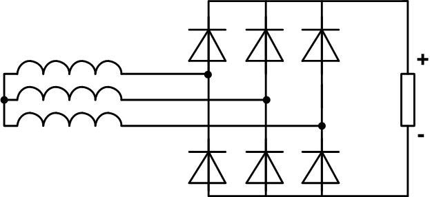
Here the amplitude of output voltage ripple is the same 14%, but the frequency is equal to the inferior frequency of the input AC voltage, so the capacitance of the filtering capacitor will be the smallest of all the presented options. And the output EMF will be twice as high as in the previous circuit.
This rectifier is used with an output transformer having a secondary winding in a "star" circuit, but the same valve assembly will be much less effective when used with a transformer whose output is included in a "delta" circuit.
Here the amplitude and frequency of the ripple is the same as in the previous scheme. But the average EMF is lower than in the previous circuit by a factor of one. Therefore, this connection is rarely used.
Rectifiers with voltage multiplication
It is possible to build a rectifier whose output voltage will be a multiple of the input voltage. For example, there are circuits with voltage doubling:
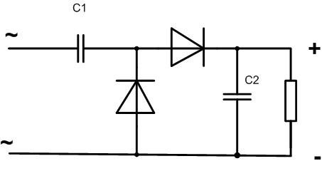
Here, capacitor C1 is charged during the negative half-period and switched in series with the positive wave of the input sine wave. The disadvantage of this construction is the low load capacity of the rectifier, as well as the fact that the capacitor C2 is under the doubled voltage value. Therefore, such a scheme is used in radio engineering for rectification with doubling of low-power signals for amplitude detectors, as a measuring body in automatic gain control circuits, etc.
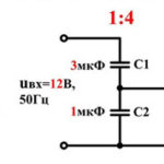
In electrical engineering and power electronics another version of the doubling circuit is used.
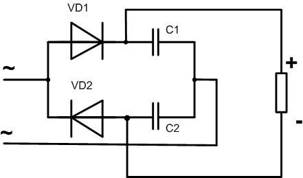
A doubler assembled according to Latour's circuit has a large load capacity. Each of the capacitors is under the input voltage, so in terms of mass and dimensions this variant also wins over the previous one. During the positive half-period the capacitor C1 is charged, during the negative half-period - C2. Capacitors are connected in series, and in relation to the load they are connected in parallel, so the voltage on the load is equal to the sum of of the voltages of the charged capacitors. The frequency of the ripple is equal to twice the frequency of the line voltage, and the value depends on on the value of the capacitors. The higher they are, the lower the ripple. And here it is necessary to find a reasonable compromise.
The disadvantage of the circuit is the prohibition of grounding one of the load terminals - one of the diodes or capacitors will be shorted in this case.
This circuit can be cascaded any number of times. Thus, by repeating the switching principle twice, you can get a circuit with voltage quadrupling, etc.
The first capacitor in the circuit must be able to withstand the voltage of the power supply, the others must be able to double the supply voltage. All gates must be designed for double reverse voltage. Of course, for reliable operation of the circuit, all parameters must have at least 20% margin.
If there are no suitable diodes, you can connect them in series - this will increase the maximum allowable voltage by a multiple. But parallel to each diode must be included equalizing resistors. It is necessary to do this, because otherwise due to the variation of parameters of the gates the reverse voltage can be distributed unevenly between the diodes. The result can be the highest value for one of the diodes. And if each element of the chain is shunted with a resistor (their rating must be the same), then the reverse voltage will be distributed strictly the same. Resistance of each resistor should be about 10 times less than reverse resistance of the diode. In this case the effect of additional elements on the circuit operation will be minimized.
Parallel connection of diodes in this circuit is unlikely to be needed, the currents here are small. But it can be useful in other rectifier circuits where the load draws serious power. Parallel connection multiplies the allowable current through the valve, but screws up the parameter deviation. As a result, one diode can take the most current and not sustain it. To avoid this, a resistor is put in series with each diode.
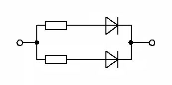
The rating of the resistor is chosen so that at the maximum current the voltage drop across it is 1 volt. So, for a current of 1 A, the resistance should be 1 ohm. The power in this case should be at least 1 watt.
In theory, the voltage multiplicity can be increased to infinity. In practice, remember that the load capacity of such rectifiers drops sharply with each additional stage. As a result, it is possible to come to the situation, when the voltage sag on the load will exceed the multiplicity of multiplication and will make the rectifier work senseless. This disadvantage is inherent in all such circuits.
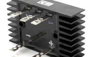
Often such voltage multipliers are produced as a single module in good insulation. Such devices were used, for example, to create high voltage in TV sets or oscilloscopes with a cathode ray tube as a monitor. Doubling circuits using chokes are also known, but they are not widespread - the winding parts are difficult to make and not very reliable in operation.
There are quite a lot of rectifier schemes. Given the wide range of applications of this unit, it is important to approach the choice of circuit and calculation of elements consciously. Only in this case, a long and reliable operation is guaranteed.
Related articles: