Switching power supplies are used to convert the input voltage to the value needed by the internal elements of a device. Another widely used name for switching power supplies is inverters.
Contents
What is a switching power supply?
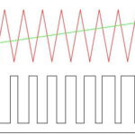
An inverter is a secondary power supply that uses a double conversion of the input AC voltage. The output values are adjusted by changing the duration (width) of the pulses and, in some cases, the frequency of their repetition. This type of modulation is called pulse width modulation.
The principle of operation of a switching power supply
The basic principle of the inverter is to rectify the primary voltage and then convert it into a train of high frequency pulses. This is what distinguishes it from a conventional transformer. The output voltage of the unit serves to form a negative feedback signal, which allows to regulate the pulse parameters. By controlling the pulse width, it is easy to arrange stabilization and regulation of output parameters, voltage or current. That is, it can be a voltage regulator as well as a current regulator.
The number and polarity of the output values can be very different, depending on how the switching power supply works.
Varieties of power supplies
Several types of inverters have found use, which differ in the circuit design:
- transformerless;
- transformer.
The first are distinguished by the fact that the pulse sequence goes directly to the output rectifier and smoothing filter of the device. Such a circuit has a minimum of components. A simple inverter includes a specialized integrated circuit - a pulse-width oscillator.
The main disadvantage of transformerless devices is that they have no galvanic isolation from the power supply network and can pose a risk of electric shock. They also usually have low power and deliver only 1 value of output voltage.
More common are transformer devices, in which a high-frequency pulse sequence goes to the primary winding of the transformer. There can be as many secondary windings as you want, allowing several output voltages to be formed. Each secondary winding is loaded with its own rectifier and smoothing filter.
A powerful switching-mode power supply of any computer is built according to such a circuit, which has high reliability and safety. For the feedback signal here a voltage of 5 or 12 volts is used, because these values require the most accurate stabilization.
The use of transformers for high-frequency voltage conversion (tens of kilohertz instead of 50 Hz) allowed to reduce their size and weight many times and to use ferromagnetic materials with high coercive force as the core material (magnetic wire) instead of electrical iron.
DC-DC converters are also based on pulse width modulation. Without the use of inverter circuits, the conversion was associated with great difficulties.
Power Supply Schematic
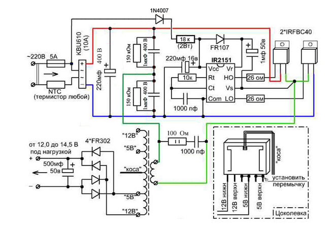
The circuitry of the most common pulse converter configuration includes:
- mains noise filter;
- rectifier
- a smoothing filter;
- pulse-width converter;
- key transistors;
- high frequency output transformer;
- output rectifiers;
- individual and group output filters.
The purpose of the interference suppression filter is to trap interference from the operation of the device into the supply network. The switching of powerful semiconductor elements can be accompanied by the creation of short-term pulses in a wide frequency spectrum. Therefore it is necessary here to use specially designed elements as pass-through capacitors of the filtering links.
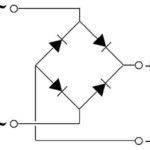
A rectifier is used to convert the input AC voltage to DC, and a downstream smoothing filter eliminates ripples in the rectified voltage.
When a DC converter is used, the rectifier and filter are unnecessary, and the input signal, after passing through the noise filter circuit, is fed directly to the pulse-width converter (modulator), abbreviated PWM.
PWM is the most complex part of a switching power supply circuit. Its task includes:
- Generation of high-frequency pulses;
- control of unit output parameters and pulse train correction in accordance with the feedback signal;
- monitoring and protection against overloads.
The PWM signal is fed to the control pins of the power key transistors in a bridge or half-bridge circuit. The power leads of the transistors are loaded into the high-frequency output transformer's primary winding. Traditional bipolar transistors are replaced with IGBT or MOSFET transistors, which have a low junction voltage drop and high speed performance. The improved parameters of the transistors help to reduce power dissipation while maintaining the same size and technical design parameters.
The output pulse transformer uses the same conversion principle as the classical transformer. The exception is the operation at an increased frequency. As a consequence, high-frequency transformers with the same transmitted power have smaller dimensions.
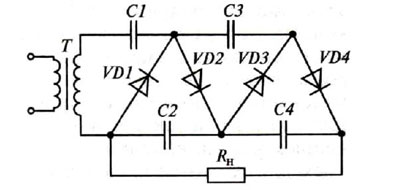
The voltage from the secondary winding of the power transformer (there can be several) goes to the output rectifiers. Unlike the input rectifier, the rectifier diodes of the secondary circuit must have a higher operating frequency. Schottky diodes work best in this section of the circuit. Their advantages over conventional diodes are:
- high operating frequency;
- lower capacitance of p-n junction;
- low voltage drop.
The purpose of the output filter of a switching-mode power supply is to reduce the ripple of the rectified output voltage to the necessary minimum. Since the ripple frequency is much higher than the line voltage, there is no need for high capacitance and inductance in the coils.
Scope of application of the switched-mode power supply
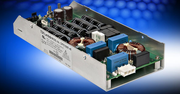
Pulse voltage converters are used in most cases instead of traditional transformer ones with semiconductor stabilizers. With the same power, inverters are characterized by smaller overall dimensions and weight, high reliability, and most importantly - higher efficiency and the ability to work in a wide range of input voltages. And with comparable dimensions, the maximum power of the inverter is several times higher.
In such an area as DC voltage conversion, pulse sources have almost no alternative and are able to work not only to reduce voltage, but also to produce higher voltage, organize polarity reversal. High conversion frequency greatly facilitates filtering and stabilization of output parameters.
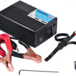
Small-sized inverters on specialized integrated circuits are used as chargers for all kinds of gadgets, and their reliability is such that the service life of the charging unit can exceed the service life of a mobile device several times over.
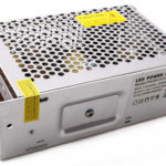
12 volt power drivers for switching on LED light sources are also based on a pulse circuit.
How to make a switching power supply with your own hands
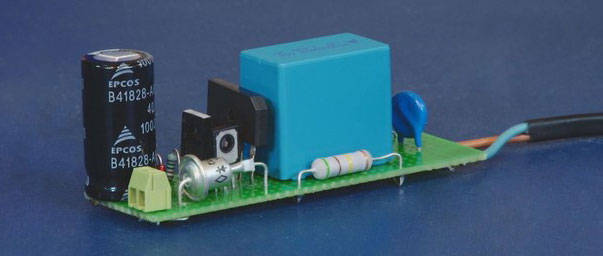
Inverters, especially powerful ones, have complex circuitry and are available for replication only to experienced radio amateurs. We can recommend simple low-power circuits with specialized PWM controller chips for self-assembly of mains power supplies. Such ICs have a small number of elements of piping and have well-tested typical switching circuits, which practically do not require adjustment and tuning.
When working with homemade designs or repairing industrial devices, remember that part of the circuit will always be under the potential of the network, so safety precautions must be observed.
Related articles: