The pair "optical transmitter - optical receiver" has long been used in electronics and electrical engineering. An electronic component in which the receiver and transmitter are located in the same enclosure and there is optical communication between them is called an optocoupler or optocoupler.
Contents
Optron Design
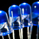
Optrons consist of an optical transmitter (emitter), an optical channel and an optical receiver. The phototransmitter converts an electrical signal into an optical signal. The transmitter in most cases is an LED (early models used incandescent or neon bulbs). The use of LEDs is unprincipled, but they are more durable and reliable.
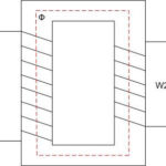
The optical signal is transmitted through an optical channel to the receiver. The channel can be closed - when the light emitted by the transmitter does not go beyond the body of the optocoupler. Then the signal generated by the receiver is synchronized with the signal at the input of the transmitter. These channels can be air-filled or filled with a special optical compound. There are also "long" optocouplers in which the channel is fiber optic.
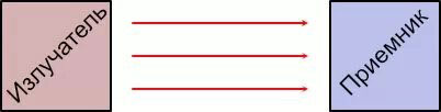
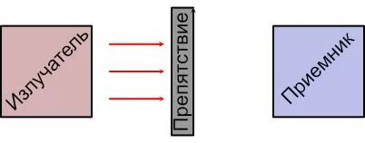
If the optocoupler is designed so that the generated radiation leaves the enclosure before reaching the receiver, it is called an open channel. It can be used to detect obstacles in the path of the light beam.
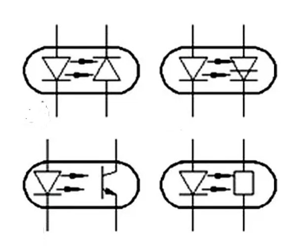
The photodetector converts the optical signal back into an electrical signal. The most commonly used receivers are:
- Photodiodes. Typically used in digital communication lines. They have a small linear section.
- Photoresistors. Their feature is the two-way conductivity of the receiver. The current through the resistor can go in either direction.
- Phototransistors. A feature of such devices is the ability to control the transistor current through both the opto-transistor and the output circuit. They are used in both linear and digital modes. A separate type of optocouplers are those with field-effect transistors switched in parallel. These devices are called Solid state relays.
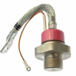
- Photothyristors. Such optocouplers are characterized by increased output power and switching speed, such devices are convenient for controlling elements of power electronics. These devices also belong to the category of solid-state relays.
Optocoupler microcircuits - optocoupler assemblies with optocoupler wiring in one package - have become widespread. Such optocouplers are used as switching devices and for other purposes.
Advantages and disadvantages
The first advantage noted in optical devices is the absence of mechanical parts. This means that during operation there is no friction, wear and tear, sparking contacts, as with electromechanical relays. Unlike other devices for signal galvanic isolation (transformers, etc.) optocouplers can operate at very low frequencies, including direct current.
In addition, the advantage of optical isolators is the very low capacitive and inductive coupling between input and output. This reduces the probability of transmission of pulse and high-frequency interference. The absence of mechanical and electrical coupling between the input and output provides a variety of technical solutions for creating non-contact control and switching circuits.
Although real-world designs are limited in voltage and current for input and output, there are no fundamental theoretical obstacles to increasing these characteristics. This allows optocouplers to be built to suit almost any application.
The disadvantages of optocouplers include one-way signal transmission - you cannot transmit an optical signal from the photodetector back to the transmitter. This makes it difficult to organize a feedback loop to match the response of the receiver circuit to the transmitter signal.
The response of the receiving part can be influenced not only by changing the transmitter radiation, but also by influencing the state of the channel (the appearance of foreign objects, changes in the optical properties of the channel medium, etc.). Such influence can be of non-electrical nature. This expands the possibilities of using optocouplers. Insensitivity to external electromagnetic fields allows you to create data channels with high noise immunity.
The main disadvantage of optrons include low energy efficiency associated with signal losses in the double conversion of the signal. Also considered a disadvantage is the high intrinsic noise level. This reduces the sensitivity of optocouplers and limits their application where weak signals are required.
When using optocouplers it is necessary to consider the influence of temperature on their parameters - it is significant. In addition, the disadvantages of optocouplers include a noticeable degradation of elements during operation and a certain lack of technology in production associated with the use of different semiconductor materials in one package.
Optocoupler characteristics
Optocoupler parameters are divided into two categories:
- Characterizing the properties of the device to transmit a signal;
- characterizing the decoupling between input and output.
The first category is the current transfer coefficient. It depends on the emissivity of the LED, the sensitivity of the receiver and the properties of the optical channel. This coefficient is equal to the ratio of output current to input current and for most types of optocouplers is 0.005 ... 0.2. Transistor elements have a transfer coefficient of up to 1.
If we consider an optocoupler as a quadrupole, its input characteristic is completely determined by the voltmeter (LED), and the output characteristic is determined by the receiver characteristic. The input characteristic in general is nonlinear, but some types of optocouplers have linear sections. For example, a good linearity has a part of the WAV of a diode optocoupler, but this section is not very large.
Resistor elements are also evaluated by the ratio of dark resistance (at an input current equal to zero) to the light resistance. For thyristor optocouplers an important characteristic is the minimum holding current in the open state. The highest operating frequency is also an important characteristic of an optocoupler.
The quality of galvanic isolation is characterized by:
- the greatest voltage applied to the input and to the output;
- the greatest voltage between input and output;
- insulation resistance between input and output;
- the throughput capacitance.
The last parameter characterizes the ability of the electrical high-frequency signal to leak from the input to the output, bypassing the optical channel, through the capacitance between the electrodes.
There are parameters to determine the capabilities of the input circuit:
- The greatest voltage that can be applied to the input leads;
- The largest current the LED can handle;
- The voltage drop across the LED at the rated current;
- reverse input voltage - the reverse polarity voltage that the LED can handle.
For the output circuit, these characteristics will be the highest allowable current and voltage output, and the leakage current at zero input current.
Applications for optocouplers
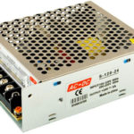
Optocouplers with a closed channel are used where for some reason (electrical safety, etc.) a decoupling between signal source and receiver is required. For example, in the feedback circuits of switching power supplies - the signal is taken from the output of the PSU, fed to the emitting element, the brightness of which depends on the voltage level. A signal depending on the output voltage is taken from the receiver and fed to the PWM controller.
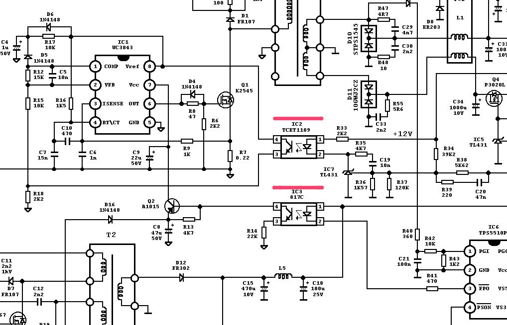
A schematic of a computer PSU with two optocouplers is shown in the figure. The upper optocoupler IC2 creates a voltage stabilizing feedback. The lower IC3 operates in discrete mode and supplies power to the PWM IC when the standby voltage is present.
Galvanic isolation between source and receiver is also required by some standard electrical interfaces.
Devices with an open channel are used to create sensors for detecting any objects (presence of paper in a printer), limit switches, counters (objects on a conveyor belt, number of gear teeth in mouse manipulators), etc.
Solid state relays are used in the same way as conventional relays - for switching signals. But their proliferation is constrained by the high resistance of the channel in the open state. They are also used as drivers for elements of solid-state power electronics (high-power field-effect or IGBT transistors).
The optron was developed over half a century ago, but its widespread use began after LEDs became available and inexpensive. Now all new models of optocouplers (mostly chips based on them) are being developed, and their field of application is only expanding.
Related articles: