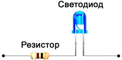
The main parameter that affects the life of the LED, is the electric current, the value of which is strictly regulated for each type of LED-element. One common way to limit the maximum current is to use a limiting resistor. The resistor for the LED can be calculated without complex calculations based on Ohm's law, using the technical values of the diode parameters and the voltage in the switching circuit.
Contents
Features of the LED connection
Working on the same principle as the rectifier diodes, light-emitting elements, however, have distinctive features. The most important of these are:
- Extremely negative sensitivity to reverse polarity voltages. LED included in a circuit with the wrong polarity fails almost immediately.
- Narrow range of permissible operating current through p-n junction.
- The dependence of the transition resistance on the temperature, which is characteristic of most semiconductor elements.
The last point should be considered in more detail, because it is the main point for the calculation of the quenching resistor. The documentation for radiating elements specifies the allowable range of nominal current, at which they keep working and provide the specified characteristics of radiation. Underestimation of the value is not fatal, but leads to some decrease in brightness. From a certain limit value, the current flow through the junction stops and there will be no luminescence.
Exceeding the current first leads to an increase in the brightness of the glow, but the service life is sharply reduced. A further increase leads to the failure of the element. Thus, the selection of the resistor for the LED aims at limiting the maximum allowable current in the worst conditions.
The voltage at the semiconductor junction is limited by the physical processes on it and is in a narrow range of about 1-2 V. 12 volt light emitting diodes, often installed on cars, may contain a chain of series-connected elements or a limiting circuit included in the design.
Why do you need a resistor for a LED?
The use of limiting resistors when turning on the LED is not the most effective, but the easiest and cheapest solution to limit the current within acceptable limits. Circuit solutions that allow you to stabilize the current in the emitter circuit with high accuracy are quite difficult to replicate, and ready-made have a high cost.
The use of resistors allows you to perform lighting and illumination in-house. The main thing is to know how to use measuring instruments and minimal soldering skills. Properly calculated limiter, taking into account possible tolerances and temperature fluctuations can ensure the proper functioning of LEDs throughout the declared service life at a minimum cost.
Parallel and series switching of LEDs
In order to combine the parameters of power circuits and characteristics of LEDs are widespread series and parallel connection of several elements. Each type of connection has both advantages and disadvantages.
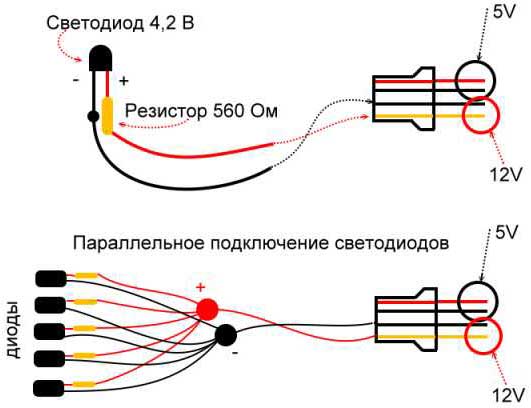
Parallel connection
The advantage of such a connection is the use of only one limiter for the entire circuit. It should be stated that this advantage is the only one, so the parallel connection is almost nowhere to be found, except in low-grade industrial products. The disadvantages are as follows:
- The power dissipation on the limiting element increases in proportion to the number of LEDs connected in parallel.
- The variation of the element parameters leads to uneven distribution of currents.
- Burnout of one of the emitters leads to an avalanche-like failure of all the others due to the increase in the voltage drop of the parallel connected group.
A connection where the current through each radiating element is limited by a separate resistor somewhat increases the operational properties. More precisely, it is a parallel connection of separate circuits consisting of LEDs with limiting resistors. The main advantage is great reliability, because the failure of one or more elements in no way affects the operation of the others.
The disadvantage is the fact that due to the variation of LED parameters and the technological tolerance of the resistance rating, the brightness of the luminescence of individual elements can vary greatly. Such a circuit contains a large number of radio elements.
Parallel connection with individual limiters is used in circuits with low voltage, starting from a minimum, limited by the voltage drop across the p-n junction.
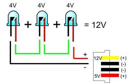
Series connection
Series connection of radiating elements is the most widely used because the undoubted advantage of a series circuit is the absolute equality of the current flowing through each element. Since the current through the single limiting resistor and through the diode is the same, the power dissipation will be minimal.
A significant disadvantage is that a failure of at least one of the elements will lead to the inoperability of the whole chain. The series connection requires a higher voltage, the minimum value of which increases in proportion to the number of elements included.
Mixed connection
Using a large number of emitters is possible by making a mixed connection, using several parallel connected chains, and connecting one limiting resistor and several LEDs in series.
If one element burns out, only one circuit in which the element is installed will be inoperative. The others will function properly.
Formulas for calculating a resistor
The calculation of resistor resistance for LEDs is based on Ohm's law. The initial parameters for how to calculate the resistor for an LED are:
- circuit voltage;
- operating current of the LED;
- voltage drop across the emitting diode (supply voltage of the LED).
The value of the resistance is determined from the expression:
R = U/I,
where U is the voltage drop across the resistor, and I is the direct current through the LED.
The voltage drop of the LED is determined from the expression:
U = Upit - Usv,
where Upit - circuit voltage, and Ucd - nameplate voltage drop across the emitting diode.
Calculation of LED for the resistor gives the resistance value, which will not be in the standard range of values. Take the resistor with the resistance closest to the calculated value on the larger side. In this way a possible voltage increase is taken into account. It is better to take the value next in the series of resistances. This will slightly reduce the current through the diode and reduce the brightness of the glow, but it will level out any change in the supply voltage and the diode resistance (for example, when the temperature changes).
Before selecting the resistance value, you should estimate the possible decrease in current and brightness compared to the set value using the formula:
(R - Rst)R-100%.
If the resulting value is less than 5%, then you need to take a larger resistance, if from 5 to 10%, then you can limit yourself to a smaller one.
An equally important parameter that affects the reliability of operation is the power dissipation of the current limiting element. Current flowing through the section with resistance, causes its heating. To determine the power that will be dissipated, use the formula:
P = U-U/R
Use a limiting resistor whose allowable power dissipation will exceed the calculated value.
Example:
There is a LED with a voltage drop of 1.7 V and a nominal current of 20 mA. It must be connected to a circuit with a voltage of 12 V.
The voltage drop across the limiting resistor is:
U = 12 - 1.7 = 10.3 V
Resistance of the resistor:
R = 10.3/0.02 = 515 ohms.
The closest higher value in the standard range is 560 Ohm. At this value, the decrease in current compared to the set value is a little less than 10%, so there is no need to take a larger value.
Power dissipation in watts:
P = 10.3-10.3/560 = 0.19 W.
So, for this circuit, an element with an allowable power dissipation of 0.25 W can be used.
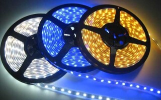
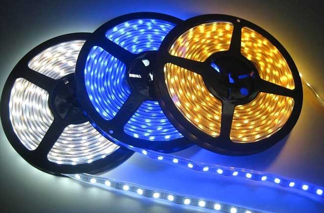
Connection of LED strips
LED strips are available at different supply voltages. The strip has a circuit of diodes in series. Number of diodes and the resistance of the terminating resistors depend on the supply voltage strip.
The most common types of LED strips are designed for connection to a circuit with a voltage of 12 V. Using a higher voltage for operation is also possible here. In order to properly calculate the resistors, it is necessary to know the current flowing through a single section of tape.
Increasing the length of the tape causes a proportional increase in the current, because the minimum sections are technologically connected in parallel. For example, if the minimum length of a section is 50 cm, then a tape of 5m of 10 such sections will have a 10 times increased current consumption.
Related articles: