To control heavy loads in AC circuits electromagnetic relays are often used electromagnetic relays. The contact groups of these devices are an additional source of unreliability due to their tendency to burn or weld. Also a disadvantage looks the possibility of arcing when switching, which in some cases requires additional safety measures. Therefore, electronic keys look preferable. One variant of such a key is made on triacs.
Contents
What is a triac and why do we use it?
One of the following is often used as a controlled switching element in power electronics Thyristors - Thyristors. Their advantages are:
- No contact group;
- No rotating or moving mechanical elements;
- Low weight and dimensions;
- long service life, independent of the number of cycles of switching on and off;
- low cost;
- high speed and quiet operation.
But when trinistors are used in AC circuits, their one-way conductivity becomes a problem. For the trinistors to pass current in both directions, we have to go to tricks in the form of parallel connection in the opposite direction of two trinistors, controlled simultaneously. It seems logical to combine these two trinistors in one shell for ease of installation and size reduction. And this step was made in 1963, when Soviet scientists and specialists of General Electric almost simultaneously applied for registration of the invention of a symmetrical trinistor - simistor (in foreign terminology, triac - triode for alternative current).

In fact, a triac is not literally two trinistors in one case.
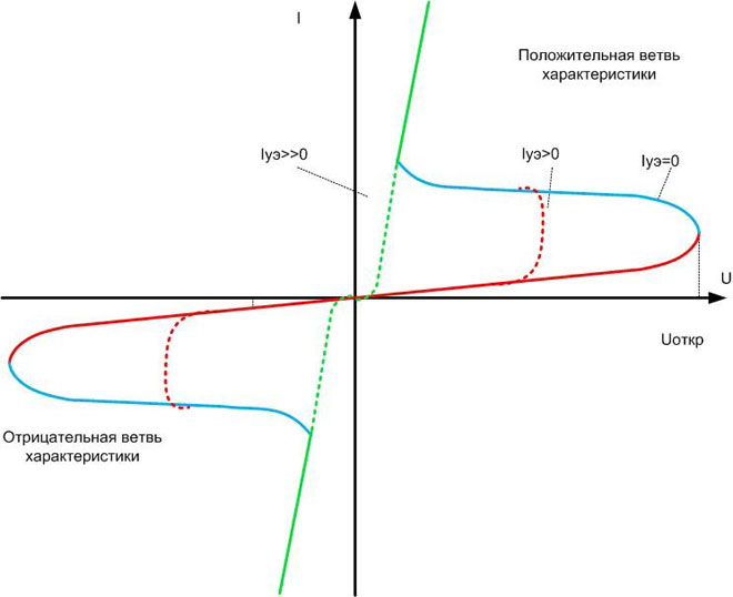 The whole system is implemented on a single crystal with different p- and n-conductance zones, and this structure is not symmetrical (although the volt-ampere characteristic of a triac is symmetrical about the origin and is a mirror image of the BAC of a trinistors). And this is the fundamental difference between a triac and two trinistors, each of which must be controlled by a positive, with respect to the cathode, current.
The triac has no anode and cathode in relation to the direction of current flow, but in relation to the control electrode, these leads are unequal. The terms "conditional cathode" (MT1, A1) and "conditional anode" (MT2, A2) are found in the literature. They are conveniently used to describe the operation of a triac.
When a half-wave of any polarity is applied, the device is latched first (red section of the VAC). Also, as with a trinistors, triacs can be unlocked when the voltage threshold is exceeded at any polarity of the sine wave (blue section). In electronic switches, this phenomenon (dynistor effect) is rather harmful. It should be avoided when selecting the mode of operation. The triac opens by applying current to the control electrode. The higher the current, the earlier the key opens (red dashed area). This current is created by applying a voltage between the control electrode and the conditional cathode. This voltage must be either negative or the same sign as the voltage applied between MT1 and MT2.
At a certain value of current, the triac opens immediately and behaves like a normal diode - until it locks (green dashed and solid areas). Improvements in technology lead to a reduction of the current consumption for complete unlocking of the triac. With modern modifications it is up to 60 mA and below. But do not get carried away with lower current in the real circuit - it can lead to unstable opening of the triac.
Closing, as with a normal trinistors, occurs when the current decreases to a certain limit (almost to zero). In an AC circuit, this occurs when the circuit passes through zero again, after which the control pulse must be applied again. In DC circuits, controlled closing of the triac requires cumbersome technical solutions.
Features and Limitations
There are limitations to using a triac when switching reactive (inductive or capacitive) loads. When such a load is present in an AC circuit, the voltage and current phases are shifted in relation to each other. The direction of the shift depends on the nature of the reactive component, and the magnitude the magnitude of the reactive component. It has already been said that the triac is switched off when the current passes through zero. And the voltage between MT1 and MT2 at that moment can be quite large. If the rate of change of voltage dU/dt exceeds the threshold value, the triac may not close. To avoid this effect the triac is connected in parallel to the power path of the triac varistors. Their resistance depends on the applied voltage, and they limit the rate of change of the potential difference. The same effect can be achieved by using an RC-chain (snubber).
The danger of exceeding the rate of current rise during load switching is related to the finite triac open time. At the moment when the triac has not yet closed, it may be that a large voltage is applied to it and at the same time a rather large through current is flowing through the power path. This can cause the device to emit a lot of heat, and the crystal can overheat. To eliminate this defect it is necessary to compensate, if possible, the reactance of the consumer by series inclusion in the circuit of reactance of approximately the same value, but of the opposite sign.
It should also be kept in mind that in the open state the triac drops about 1-2 V. But since the application is high-power high-voltage switches, this property does not affect the practical application of triacs. A loss of 1-2 volts in a 220 volt circuit is comparable to a voltage measurement error.
Examples of use
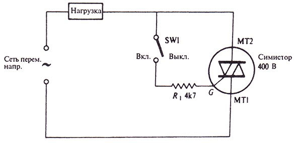
The main use of a triac is as a switch in an AC circuit. There is no fundamental limitation for using a triac as a DC switch, but there is no point in doing so either. In this case, it is easier to use the cheaper and more common trinistors.
Like any key, the triac is connected in series with the load. Turning the triac on and off controls the voltage supply to the consumer.
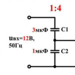
The triac can also be used as a voltage regulator on loads that do not care about voltage waveforms (such as incandescent lamps or thermoelectric heaters). In this case, the control circuit looks like this.
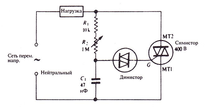
Here the phase reversing circuit is organized on the resistors R1, R2 and capacitor C1. By adjusting the resistance we achieve a shift of the beginning of the pulse with respect to the zero crossing of the mains voltage. A dynistor with an opening voltage of about 30 volts is responsible for forming the pulse. When this level is reached, it opens and passes current to the control electrode of the triac. Obviously, this current coincides in direction with the current through the power path of the triac. Some manufacturers make semiconductor devices called Quadrac. They have a triac and a diistor in the control electrode circuit in the same enclosure.
This circuit is simple, but its current consumption has a sharply non-sinusoidal shape, and interference is created in the mains. To suppress them, you should use filters - at least the simplest RC-chains.
Advantages and disadvantages
The advantages of the triac are the same as those of the trinistors described above. To them we should only add the possibility of operation in AC circuits and easy control in this mode. But there are also disadvantages. Mainly they concern the area of application, which is limited by the reactive component of the load. The protection measures suggested above can not always be applied. Also, the disadvantages should include:
- Increased sensitivity to noise and interference in the circuit of the control electrode, which can cause false positives;
- The need to remove heat from the crystal - the arrangement of heat sinks compensates for the small size of the device, and for switching heavy loads the use of contactors and relays becomes preferable;
- limitation on operating frequency - it does not matter when working at industrial frequencies of 50 or 100 Hz, but it limits the use in voltage converters.
For competent use of triacs it is necessary to know not only the principles of operation of the device, but also its disadvantages, defining the limits of application of triacs. Only in this case the developed device will work long and reliably.
Related articles: