Switching processes are fundamental in all automated control systems. The most common switching elements are intermediate electromagnetic relays.
Despite the large number of different semiconductor devices, electromagnetic relays are still used in all kinds of industrial equipment and household appliances. The popularity of relays is due to their reliability and high performance characteristics, which directly depend on the characteristics of the metal contacts.
Contents
What is a relay and where are they used?
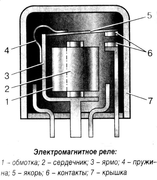
The electromagnetic relay is an accurate and reliable switching device which operates on the basis of an electromagnetic field. It has a simple construction, represented by the following elements:
- coil;
- armature;
- Fixed contacts.
The electromagnetic coil is fixed to the base with a ferromagnetic core inside and a spring-loaded armature attached to the yoke to return to its normal position when the relay is de-energized.
Simply put, the relay ensures that an electrical circuit opens and closes according to incoming commands.
Electromagnetic relays are reliable in operation, so they are used in a variety of industrial and household appliances and equipment.
Main types and technical characteristics of electromagnetic relays
There are the following types:
- Current relay - On its principle of operation does not practically differ from voltage relay. The principal difference is only in the design of the electromagnetic coil. For the current relay the coil is wound with a large cross-section wire, and contains a small number of turns, so that it has a minimum resistance. The current relay can be connected via a transformer or directly to the contact line. In either case it correctly monitors the current intensity in the network to be controlled, and all switching operations can be carried out on this basis.
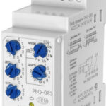
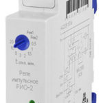
- time relays (timers) - provides a time delay in control networks, necessary in some cases for switching devices in accordance with a certain algorithm. Such relays have an extended range of settings necessary to ensure high accuracy of their operation. There are separate requirements to any time timer. For example, low power consumption, small size, high accuracy of operation, the presence of powerful contacts, etc. It is worth noting that for time relaysThe main thing is that they must be of a robust design since they have to operate constantly under increased loads. The main thing is that they should have a robust design and have high reliability, because they have to constantly function under increased loads.
Each type of electromagnetic relay has its own specific parameters. During the selection of the necessary elements, it is worth paying attention to the composition and properties of the contact pairs, decide on the power feature. Then it is necessary to study their main characteristics:
- Voltage or current of operation - the minimum value of current or voltage at which the contact pairs of the electromagnetic relay are switched.
- Release voltage or current - the maximum value that controls the armature stroke.
- Sensitivity - is the minimum amount of power required to activate the relay.
- Resistance of the winding.
- Operating voltage and current - the values of these parameters that are necessary for optimal operation of the electromagnetic relay.
- Tripping time - the period of time from the start of power supply to the relay contacts until the relay is energized.
- Release time - time during which the armature of the electromagnetic relay will return to its original position.
- Frequency of switching is the number of times the electromagnetic relay will trip within the allotted time interval.
Contact and non-contact
According to the design features of the actuating elements, all electromagnetic relays are divided into two types:
- Contact - have a group of electrical contacts, which ensure the operation of the element in the electrical network. Switching is carried out by their closing or opening. They are universal relays, used in almost all types of automated electrical networks.
- Non-contact - Their main feature is the absence of actuating contact elements. The switching process is carried out by adjusting the parameters of voltage, resistance, capacitance and inductance.
According to the sphere of application
Classification of electromagnetic relays according to their application area:
- control circuits;
- signaling;
- Automated emergency protection systems (SAZ, ESD).
By power of control signal
All types of electromagnetic relays have a certain sensitivity threshold and are therefore divided into three groups:
- low-power (less than 1 W);
- medium-power (up to 9 W);
- high-power (more than 10 W).
According to the speed of control
Any electromagnetic relay is characterized by the speed of the control signal, and therefore they are divided into:
- adjustable;
- delayed;
- fast-acting;
- inertialess.
According to the type of control voltage
Relays are divided into the following categories:
- DC (DC);
- AC (AC).
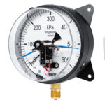
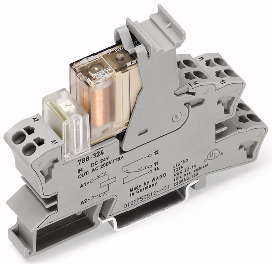
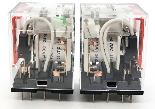
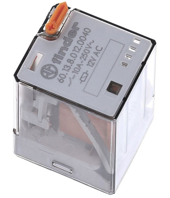
Please note! The relay coil may be designed for 24V operating voltage, but the relay contacts are quite capable of operating at up to 220V. This information is indicated on the relay body.
In the photo below you can see that the coil indicates the operating voltage of 24 VDC, i.e. 24VDC.
By degree of protection against external factors
All electromagnetic relays have the following types of construction:
- open;
- shrouded;
- sealed.
Types of Contact Groups
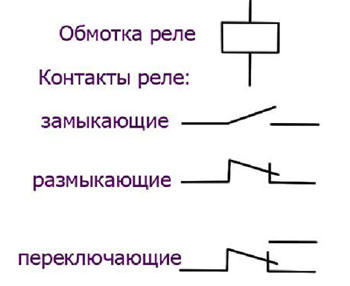
Electromagnetic relays have different configurations and design features of contact groups. Let's list the common types of elements:
- Normally Open (Normally Open - NO or Normally Open - NO) - their main feature is that the contact pairs are permanently in the open state, and triggered only after voltage is applied to the electromagnetic coil. As a result, the electrical circuit is closed and the conductors begin to function according to predetermined algorithms.
- Normally closed (Normally Closed - NC or Normally Closed - NC) - contacts are permanently closed and open when the electromagnetic relay is energized (by applying voltage to the coil).
- Change-over contacts are a combination of normally closed and open contacts. There are three contacts, common, usually designated COM, closed to common and open to common. When voltage is applied to the coil, the NC contact opens and the NO contact closes.
Electromagnetic relay models, which have several contact groups in the design, provide switching processes in several automated networks.
Note! Some relay types have a manual contact switch. It can be useful when setting up a circuit. And also an indication of the power supply of the relay coil.
Wiring diagram of the relay
On the cover of any device, the manufacturer draws a circuit diagram for connecting the electromagnetic relay to the mains. On the circuit diagram the coil of the relay is shown as a rectangle and is designated with the letter "К" with a numerical index, for example, K3. In this case the contact pairs that are not under load are marked with the letter "К" with two digits separated by a dot. e.g. K3.2 - contact number 2, relay K3. The following is an interpretation of the designation: the first digit is the serial number of the electromagnetic relay in the diagram, the second digit denotes the index of the contact pairs of the given relay.
Below is an example of an electrical circuit in which the solenoid of a pneumatic valve is controlled by the NO contact of relay K1. After closing S1 the relay is energized and the NO contacts 13, 14 are closed and a voltage is applied to the solenoid Y1.
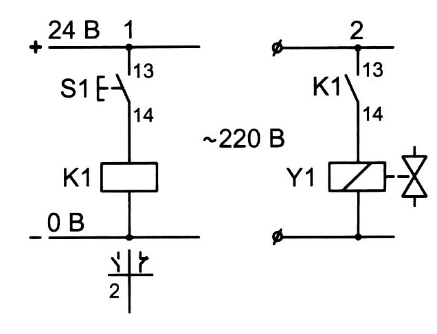
Contact pairs that are located near the electromagnetic coil, are indicated by a dashed line. In the circuit diagram of the relay all parameters of the contact pairs are necessarily displayed, the maximum permissible value of the switching current of the contacts is indicated. On the coil of the relay, the manufacturer indicates the type of current and operating voltage.
It should be noted that the connection diagram of electromagnetic relay is made for each type of element strictly individually in accordance with the peculiarities of its operation in an automated network. At the same time for the correct work of some relay types it is necessary to make an adjustment during which optimal parameters for the relay's work are set: activation delay, response current, resetting, etc.
Related articles: