When the power is out even for a few minutes, the enterprises can incur tremendous losses. And for the hospitals such situation is simply dangerous. In most facilities, it is necessary to ensure an uninterrupted power supply. To do this, it should be connected to several sources of electricity. Specialists use ATS in this approach.
Contents
What is ATS and its purpose
Automatic Transfer Switchgear or ATS is a system related to the electric panel input and output switchgear. The main purpose of the ATS is the fast connection of the load to the backup equipment. This connection is necessary when there are problems with the power supply from the main power source. The system monitors the load voltage and current and thus ensures automatic switching to emergency operation.
ATS is necessary if there is a backup power source (additional line or another transformer). If in an emergency situation the first source is disconnected, all work will be transferred to the alternate source. Using the ATS allows avoiding troubles caused by power outages.
Requirements to ATS
Basic requirements to ATS systems are as follows:
- It must have a high rate of power restoration.
- In the event that the main line fails, the unit must provide power to the consumer from an alternate source.
- The action is carried out once. The load must not be switched on and off several times, e.g. due to a short circuit.
- The main circuit breaker must be switched on by the automatic standby system. Until a backup power supply is available.
- The ATS system shall monitor the correct operation of the control circuit of the standby equipment.
Functioning principle of the automatic transfer to the backup power system
The basis of ATS operation is the circuit voltage control. Monitoring can be carried out with the help of any relays, as well as with the help of microprocessor control units.
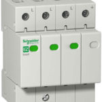
Reference! Voltage monitoring relay (also called volt controller) monitors the state of electrical potential. In the event of an overvoltage in the volt network, the controller will instantly de-energize the network.
The contact group that monitors the availability of electricity plays a major role in the ATS system. In our case it is a relay. When the voltage goes out, the control mechanism receives a signal and switches the power to the alternator. When the mains starts to work normally, the same mechanism switches the power back.
Main variants of ATS functioning logic
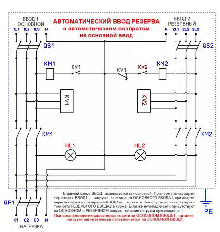
ATS system with priority of the first input
The essence of the ATS system of this type is that the load is initially connected to the power source №1. When the overload, short-circuit, phase loss or other emergency situation occurs, the load shifts to the alternate source. When the first power supply is restored to normal parameters, the load is automatically switched back.
ATS system with the second input priority
Operation logic is the same as for the previous type of system. The difference is that the load is connected to input 2. In case of failure the voltage is transferred to the input 1. After the voltage on the second source has been restored, the voltage will automatically switch to it.
ATS system with manual priority setting
Scheme of ATS system with manual selection of priority is more complicated than the ones considered above. In this case there will be a switch on the ATS system, with the help of which the ATS priority selection can be regulated.
ATS system without priority
This ATS functions from any power source. In the case when the voltage goes to input 1, and there is an emergency situation on it, the load is transferred to input 2. After stabilizing the operation of input 1, the mechanism continues to work on input 2. When an emergency occurs on the second, the voltage will switch automatically to the first.
Basic types of ATS cabinets and boards
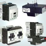
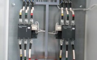
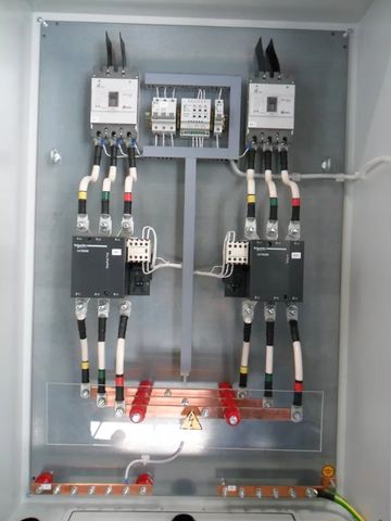
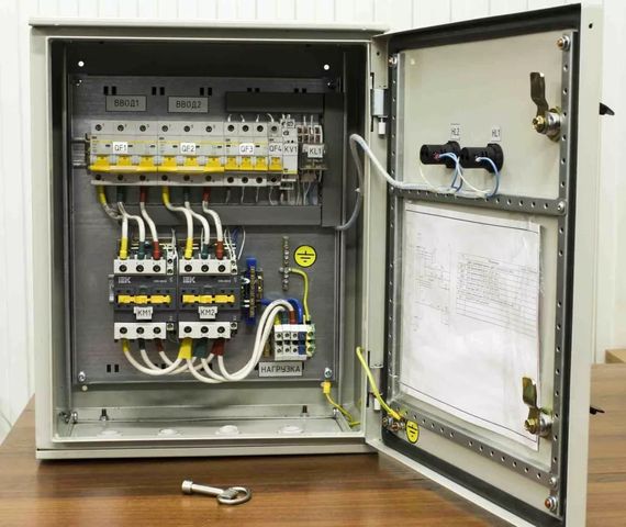
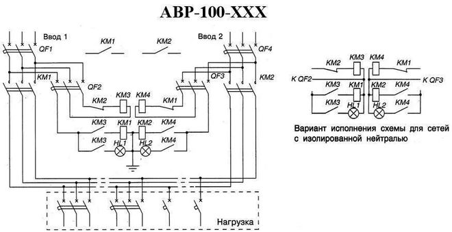
ATS panel for two inputs on contactors (starters)
Installation of the ATS cabinet on starters is the easiest way to create a backup power supply. This cabinet is the most budget variant of ATS installation. As a rule, circuit breakers are used in the ATS cabinets for 2 inputs. They are needed to protect the system from overloads and short circuits. Protection against phase imbalance and voltage spikes is provided by voltage relays. In addition, the relays become the "brain" of the whole system of automatic transfer to backup power system.
ATS cabinet with two contactors works on the following principle. Two contactors are connected to the first and the second source respectively. The first contactor is closed, and the second one has an open circuit. The electricity is fed in through port no.1.
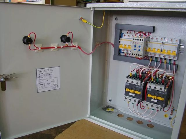
Warning! In case the ATS has the logic of the second input priority, the situation will be reversed: the circuit of the second contactor is closed, and the circuit of the first one is open.
If the first input fails and the second input fails, the second starter contacts will close and the machine will switch to it. As soon as the voltage is restored on the first input, the circuit will return to its original state.
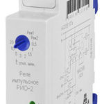
With the help of the relay here you can adjust the delay time, with which the switching from one source to another will be carried out. The optimal delay is from 5 to 10 seconds, it will protect the system against false triggering of the ATS. False triggering can occur, for example, in case of power failure.
Information! To prevent both contactors from switching on simultaneously, additional mechanical interlocks are used in the ATS boards.
The ATS panel for 2 inputs on the motor-driven circuit breakers
They are most suitable for using at rated currents 250-6300A. When the current on the main feeder fails, special electric motors receive a signal and arm the springs of the emergency circuit breaker, switching the load to the other feeder.
The main advantages of ATS motorized cabinets:
- The overload resource is much greater than that of an ATS with starters;
- It is easier to connect the buses to such a circuit breaker;
- Automatic transfer switchboard on automatic machines can also work in manual mode. In this case you can enable or disable the automatic unit with special buttons.
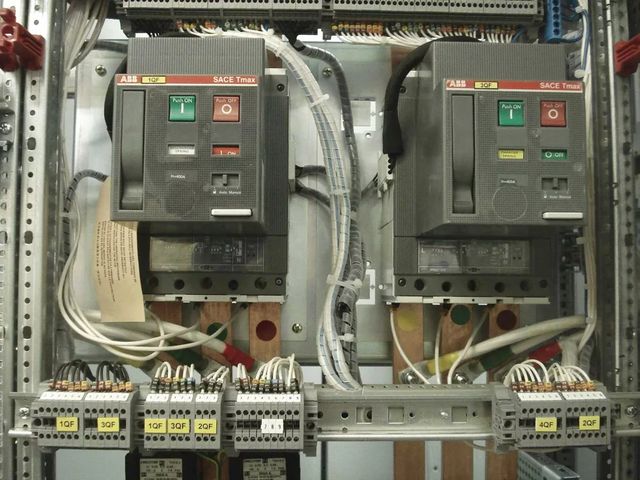
The essence of this switchboard functioning is as follows. If there is a failure on the main input, the automatics checks whether the input 2 is ready for current supply. If everything is in order, the circuit breaker spring of the second input is wound up and the power is supplied. When input 1 is able to operate normally again, the whole process goes in reverse order, supplying power to the main input.
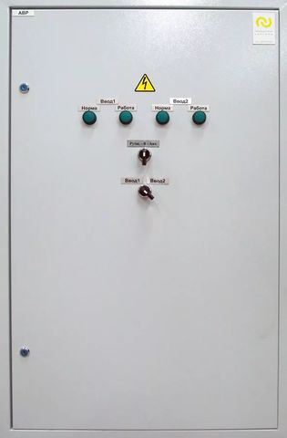
On switchboards with a motor drive, as a rule, a front panel is installed, on which all changes in the ATS can be monitored. And to prevent simultaneous actuation of two circuit breakers electrical interlocks are often used.
ATS board for 3 inputs
These cabinets are some of the most reliable power supplies. All because the ATS for 3 inputs has two spare lines, which provides the lowest possibility of power outage at the site. Usually such ATS cabinets are used when interacting with consumers of the first category of power supply reliability. They include such objects, the blackout of which poses a threat to human life or safety of the state, as well as can cause great material damage.
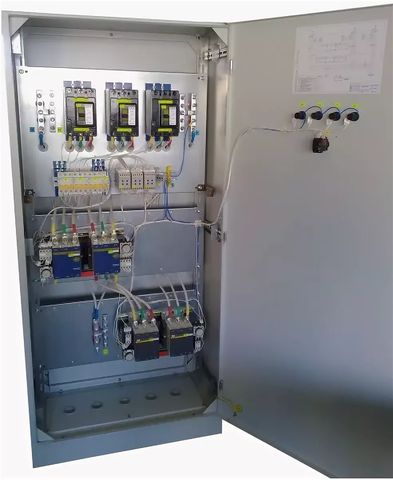
ATS panels for 3 inputs work according to two most common schemes.
The first one is when one section of consumers is fed from three independent lines. Then you can set a priority for one of the inputs, or you can work without priority. The load will be connected where the voltage is normalized.
The second scheme of functioning of the ATS panel for 3 inputs consists in the fact that two sections of consumers work from two lines, which are independent of each other. The third input is connected to the reserve power supply. In case of emergency it is connected to one of the sections.
Help! Such switchboards can be equipped with both mechanical interlocking and automatic circuit breakers with electric actuators.
Switchgear with ATS
The device is used to receive and meter electricity, as well as to protect buildings from short circuits or overloads. Switchgear cabinets with ATS used in AC networks with voltage 380/220V with a frequency of 50 Hz.
Switchgear cabinets with automatic standby are a separate panel, where both automatic and manual switching functions, as well as the accounting of electricity consumed on each line.
Switchgear cabinets consist of:
- Cable input and output unit.
- Unit of automatic reserve input.
- The unit where the consumption of electricity is metered.
Also they can be multi-panel. Then in addition they will be installed fire panels, distribution panels and others, depending on the requirements of the electrical installation.
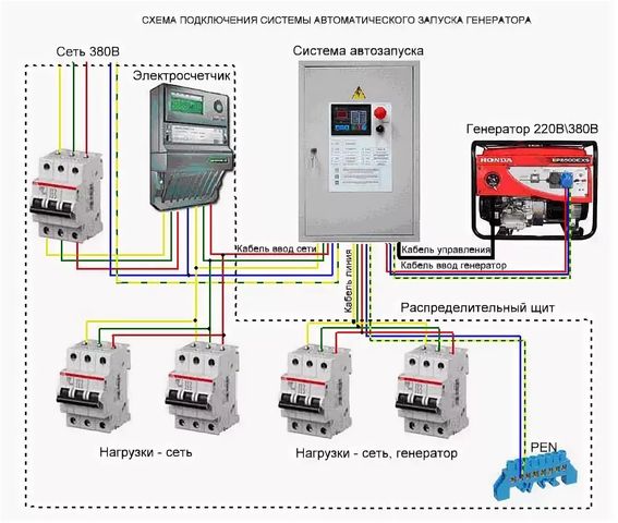
ATS switchboard for generator startup
Auxiliary power from a generator allows you to almost completely avoid total blackout. This is one of the most reliable ways to create an uninterrupted supply of electricity. ATS cabinet in this case is necessary to ensure automatic operation of the generator according to the specified algorithm.
The ATS cabinet for the generator can operate in both automatic and manual mode. Initially, it is set in automatic mode, but you can easily change it.
Important! For correct operation of the ATS-generator combination, the latter must be able to start automatically.
When the power supply is stopped on input 1, the ATS system will send a signal to start the generator. Once the generator starts functioning normally, and the voltage on the second input reaches the desired level, the mechanism will switch to the backup source. Thanks to the time relay installed, the second input will not be connected to the generator until it starts operating normally. As soon as the main (first) power supply is restored, the generator will be shut down and the power will be switched over to input 1.
In manual mode the generator is switched on and off by pressing special buttons.
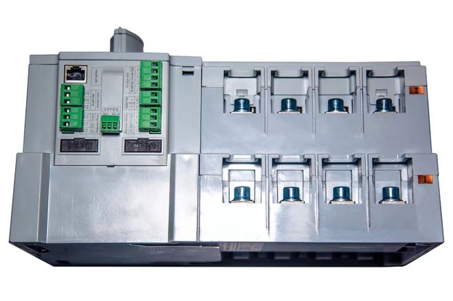
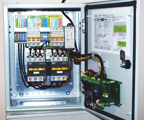
ATS UNIT
Automatic transfer switch control unit operates as part of ATS devices and performs switching from one source to another. It also monitors the state of the lines, controls contactors and magnetic starters, motors and starts the generator.
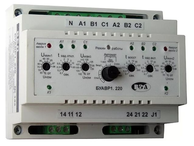
The ATS unit measures voltage in phases within a certain period of time and processes the results in real time. This allows it to determine the average voltage in each phase. The BUAVR has an increased resistance to overvoltage.
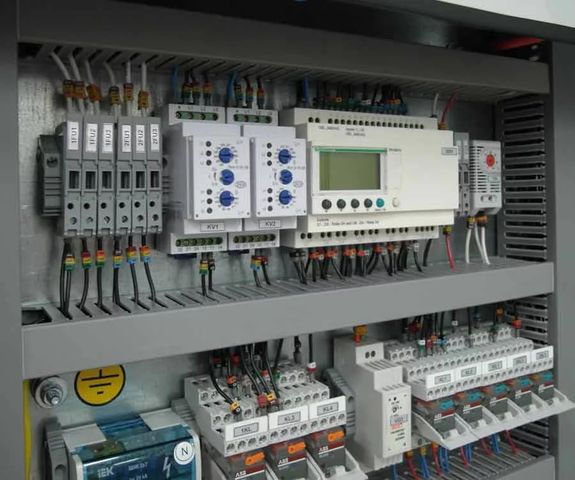
ATS Zelio Logic
Automatic transfer transfer system with the relay logic of switching between the sources. Programmable relay Zelio Logic is used. One of the main advantages of choosing such a relay is the European quality at a relatively low cost. The Zelio Logic relay is also quite simple to program. Basic knowledge is enough to use it correctly. Also, the relay has a graphical interface, which greatly simplifies the interaction.
ATS ATS
ATS ATS ATS cabinets with intelligent microprocessor units. At the moment this type of ATS cabinet is the most expensive on the market. They are most demanded at the industrial enterprises, where it is important to ensure the reliable trouble-free operation of the network and the fastest possible switching to an alternative power source. Some ATS ATSs switch from one input to another literally in two seconds. Also, such units do not need additional power supply. They operate at 480V. You can choose the most convenient algorithm, as well as automatic or manual mode.