Questions about grounding in a private home, circuit calculations and installation of the system require a mandatory solution to ensure the safety of residence. Grounding will fully perform its functions only if the right choice of scheme and compliance with all regulations and requirements. Self-assembly requires knowledge of the design principles and rules of manufacture.
Contents
- 1 Do I need grounding in a private home
- 2 Grounding schemes: which is the best to do
- 3 What is a ground loop: definition and arrangement
- 4 Types of ground loops
- 5 Rules and requirements for the ground loop
- 6 Calculation of grounding for a private house: formulas and examples
- 7 Developing a diagram
- 8 Materials for the ground loop
- 9 How to make an earthing loop assembly by yourself
- 10 Prepared sets of grounding for a private home
- 11 Features of grounding schemes of 220 and 380 V
- 12 Common installation mistakes
Do I need grounding in a private home?
When using any electrical appliance in the house, there is always a risk of wire insulation damage or shorting to the ground. In such a case, any human contact with the danger zone leads to an electric shock, which can end tragically. The current always tends to the ground and the human body becomes the conductor that connects the damaged appliance to the ground.
What does grounding provide? Essentially, it is a system that provides the shortest path for electric current. According to the law of physics, it chooses the conductor with the lowest electrical resistance, and the circuit has this property. Almost all of the current is sent to the earth electrode, and therefore only a small part of it will pass through the human body, which will not be able to cause harm. In this way, the grounding loop ensures electrical safety. Regulatory documents (GOSTs, SNIP, PUE) indicate that any private, residential building must be equipped with it at AC networks with a voltage above 40 V and AC - above 100 V.
In addition to providing safety, a grounding system increases the reliability and durability of appliances. It provides stable operation of installations, protection against overvoltages and various interferences in the network, reduces the impact of external sources of electromagnetic radiation.
Grounding should not be confused with lightning conductors (lightning rods). Although the principle of their operation is similar, they perform a different task. The function of a lightning rod is to conduct a lightning discharge into the ground when it strikes a house. In this case there is a powerful electrical charge, which should not get into the internal network, as can simply melt the wire or cable. That is why the lightning rod line runs from the receivers on the roof on the outer loop and should not coincide with the grounding, internal line. The lightning rod and grounding may have a common underground loop (if it has a reserve on the section), but the wiring must be separated.
Diagrams of grounding: what is better to do
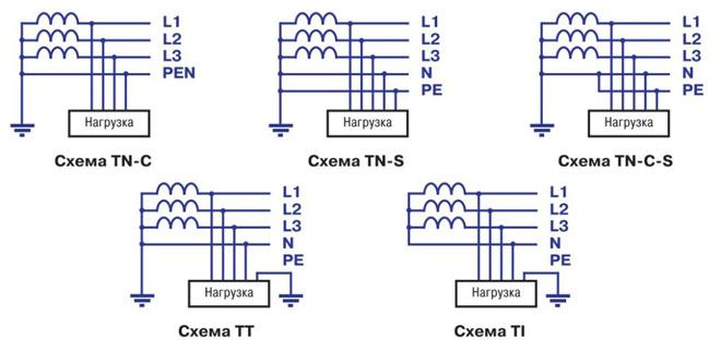
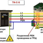
The grounding system of a private house depends on the type of mains supply to it. Most often, it is carried out according to the TN-C principle. Such a network is provided by a two-core cable or two-wire overhead line at 220 V and a four-core cable or four-wire line at 380 V. In other words, a phase (L) and a combined protective earth conductor (PEN) run to the house. In complete, modern networks, the PEN conductor is divided into separate wires - operating or neutral (N) and protective (PE) conductors, and the supply is made by a three-wire or five-wire line, respectively. Given the above options, the grounding scheme can be of 2 varieties.
TN-C-S system
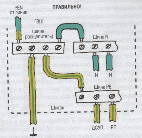
Provides for the division of the PEN feeder into parallel conductors. For this purpose, the PEN conductor is divided in the input cubicle into 3 busbars: N (neutral), PE (ground) and a splitter busbar for 4 connections. Further the N and PE conductors cannot contact each other. The PE bus is connected to the cabinet enclosure and the N conductor is mounted on insulators. The earthing circuit is brought to the splitter bus. Between the N-conductor and the earthing switch is installed jumper section of at least 10 sq.mm (copper). In further wiring, the "neutral" and "ground" do not intersect.
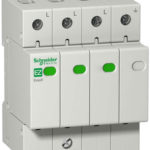
Information! It is important to note that this system is effective only when a residual current device and a residual current circuit breaker are installed.
CT system
In this circuit, it is not necessary to split conductors, as the neutral and ground conductors are already separated in a suitable network. The correct connection is simply made in the cabinet. The earthing circuit is connected to the PE wire (conductor).
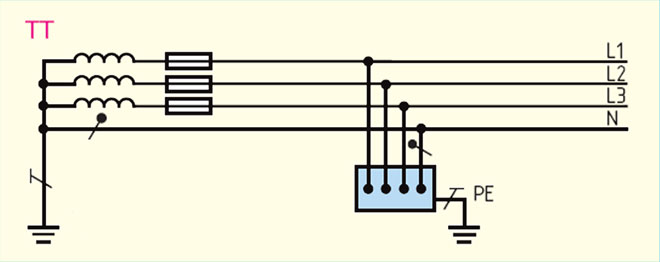
The question of which grounding system is better has no clear-cut answer. The TT scheme is easier to install and does not require additional protective devices. However, the vast majority of networks operate according to the TN-C principle, which forces the use of the TN-C-S circuit. In addition, it is not uncommon to use two-wire installations in the home. With a TN ground connection, the housing of such installations is live when the insulation fails. In this case the TN-C-S grounding is much more reliable.
What is an earthing loop: definition and construction
An earthing loop is a special structure made of electrically conductive materials with a low electrical resistance, which provides an instantaneous discharge of electric current into the ground. It consists of 2 interconnected parts - indoor and outdoor system. Their reliable connection is made in the incoming electric panel.
The device of the external subsystem must ensure the transition of the electrical signal into the ground with its distribution over the area. It is based on several electrodes buried in the ground and connected to each other in a loop by means of plates. From the plates, a busbar of sufficient cross-section, which is introduced into the electrical panel, where it connects to the internal subsystem. Each electrode is a metal pin buried (hammered in) to a certain depth.
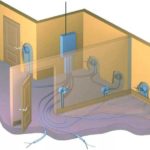
The internal sub-system is the wiring of the grounding circuit throughout the house. Conductors from the shield are taken out to the sockets, to the bodies of powerful electrical devices, to the metal trunks (pipes). Individual conductors are combined into a common bus that attaches to the bus bar of the outer loop.
The principle of operation of the grounding loop is quite simple. Electric charge, accumulated in metal elements (bodies of installations, pipelines, fittings, etc.) when the insulation of power grid conductors is damaged or induced from external sources, rushes through the wires of the internal subsystem, having low electrical resistance, to the circuit of the external subsystem. Through the electrodes buried in the ground, it "flows" into the ground. In turn, the ground has a huge capacity, which allows it to freely "absorb" such leaks of electricity.
Types of ground loops
To quickly "drain" the current into the ground, the outdoor subsystem redistributes it to several electrodes arranged in a certain order to increase the area of dissipation. There are 2 basic types of circuit connection.
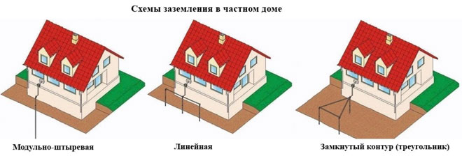
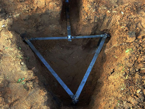
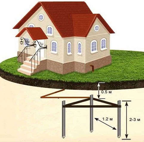
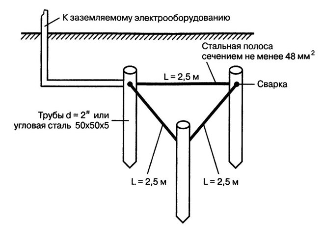
Triangle - closed loop
This case involves 3 pins connected in strips in an isosceles triangle. The distance between the electrodes is chosen according to the following principle: the minimum distance is the length of the underground part of the electrode (depth), the maximum - 2 depths. For example, for a standard burial of 2.5 m, the side of the triangle is chosen between 2.5-5 m.
Linear .
This version is made up of several electrodes arranged in a line or semicircle. Open loop is used in cases where the area of the plot does not allow to form a closed geometric figure. The distance between the pins is chosen within 1-1.5 times the depth. The disadvantage of the method is an increase in the number of electrodes.
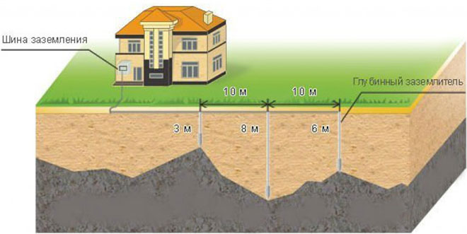
The above types are most often used in the arrangement of grounding of a private house. In principle, a closed loop can be formed in the form of a rectangle, polygon or a circle, but will require a greater number of pins. The main advantage of closed systems is that they continue to function fully when the bond between the electrodes is broken.
Important! The line circuit operates according to the daisy chain principle, and damage to the jumper puts a certain section of it out of service.
Ground loop rules and requirements
In order for the ground loop to work effectively, it must comply with certain rules:
- The outer contour must be located at least 1 m and no more than 10 m from the house. The optimum distance is 2-4 m from the foundation.
- The depth of the electrodes is chosen within 2-3 m. On the surface leave part of the pin with a length of 20-25 cm for the connection strip.
- From the input board to the circuit is laid tire section of not less than 16 mm square.
- Binding electrodes with each other is provided only by welding. In the shield, the connection can be made by bolts.
- Total system resistance shall not exceed 4 ohms for 380 V and 8 ohms for 220 V.
The external earthing circuit is located in the ground, which implies higher requirements for its design. It must be located below the frost level of the ground, because the swelling of the soil will push the electrodes out. During operation, corrosion should not destroy the metal and excessively increase its electrical resistance. The strength of the rods should allow them to be driven into hard soil.
Calculation of grounding for a private home: formulas and examples
Calculation of grounding for a private home is based on formulas for calculating the resistance to current flow for electrodes. Examples will be shown below.
Ground resistance.
With a single rod, the formula applies:
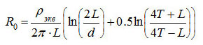
Where ρ eq is the equivalent resistivity of a single soil (chosen from Table 1 for the specific soil);
- L - length of the electrode (m);
- d - diameter of the electrode (m);
- T - distance from the middle of the electrode to the ground surface (m).
Table 1
| Soil | ρ eq, Ohm-m |
|---|---|
| Peat | 20 |
| Soil (chernozem etc.) | 50 |
| Clay | 60 |
| Sandy clay | 150 |
| Sand at groundwater up to 5 m | 500 |
| Sand with groundwater deeper than 5 m | 1000 |
Dimensions and distances for grounding electrodes
The number of electrodes in the circuit can be calculated using the formula, where:

Rn - the maximum allowable total resistance of the circuit (for 127-220 V network - 60 Ohm, for 380 V - 15 Ohm), Ψ - climate coefficient (determined from Table 2).
Table 2
| Electrode type | Climatic zone | |||
|---|---|---|---|---|
| I | II | III | IV | |
| Vertical bar | 1.8 ÷ 2 | 1.5 ÷ 1.8 | 1.4 ÷ 1.6 | 1.2 ÷ 1.4 |
| Horizontal bar | 4.5 ÷ 7 | 3.5 ÷ 4.5 | 2 ÷ 2.5 | 1.5 |
Electrode sizes are chosen based on actual conditions and recommendations:
- tube - minimum wall thickness of 3 mm, diameter - according to the availability of material;
- steel rod - diameter not less than 14 mm;
- angle - wall thickness 4 mm, size - subject to availability of material;
- electrode binding strip - width - not less than 10 mm, thickness - more than 3 mm.
Depth of burial (length of electrodes) is chosen from the condition - at least 15-20 cm below the frost level. The minimum length is 1.5 m. The pitch of the pins is 1-2 lengths of the electrode, and the minimum distance is 2 m.
Developing a scheme
Work on the arrangement of the grounding of a private home begins with the development of a grounding circuit diagram. The most popular is a closed system in the form of a triangle. Three electrodes make up its vertices, and the remaining rods are dug on its sides between the vertices. If the area near the house does not allow the construction of such a circuit, the electrodes are installed in a line, in a semicircle or "wave". It should be noted that the effectiveness of the triangular arrangement is much higher.
Materials for the ground loop
Ground loop must have high mechanical strength, low electrical resistance and the possibility of reliable connection. In addition, an important role in the choice of material is its cost.
Parameters and materials of pins
Electrodes or pins are usually made of a steel profile. This material is attractive because it can be buried by simply hammering the rods in. At the same time, its electrical resistance is quite satisfactory with a sufficient cross-section. Pins can be made of such materials:
- Rod. The most common option - a rod with a diameter of 16-18 mm. It is not recommended to use rebar, as it is subjected to calving, which leads to an increase in the specific resistance. In addition, the corrugated surface leads to irrational use of the rod section.
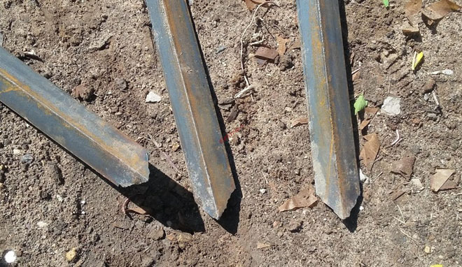
- Angle. The most commonly used angle of size 50x50 mm with a wall thickness of 4-5 mm. The lower part is sharpened to simplify hammering.
- Pipe with a diameter of over 50 mm with a wall thickness of 4-5 mm. Thick-walled pipes are recommended for hard soils and regions with frequent droughts. Holes are drilled in the bottom of such a pin. When the soil dries out, salt water is poured into the pipe, which increases the dissipation capacity of the soil.
What to make a metal bond from
Electrodes driven into the ground are connected to each other with a metal bond. It can be made of the following materials:
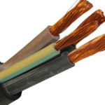
- Copper busbar or wire with a cross-section of at least 10 mm2.
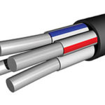
- Aluminium strip or wire of at least 16 mm cross-section2.
- Steel strip with a minimum cross-section of 48 mm2.
The most commonly used steel strip size (25-30)x5 mm. Its main advantage is the possibility of reliable welding with electrodes. When a conductor of non-ferrous metals is used as a connection, bolts are welded to the pins, on which the tires are fixed.
How to do ground loop installation yourself
Earthing installation can be done with your own hands. All the steps will be described below.
Choosing a place
It should be in the part of the site near the house, where people do not enter without an urgent need and pets. The contour is located no closer than 1 m from the foundation of the building. It is better if this area will be fenced with a low fence. All electrode points are marked on the ground. Usually a regular, isosceles triangle is built.
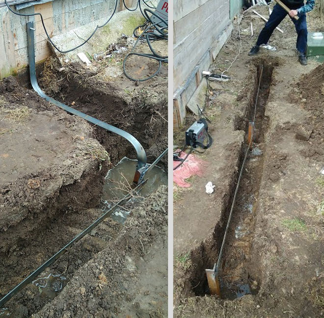
Earthwork
Along the entire marking, a trench 0.5-0.6 m deep is dug. A similar trench is dug in the course of laying the busbar that connects the circuit to the input electrical cabinet.
Assemble the structure
First, according to the scheme pins are hammered to a given depth (usually 2-2.5 m). A metal tie is welded to the tops of the pins. One strip is welded to the outermost electrode (the apex of the triangle) and laid in the trench, going to the house.
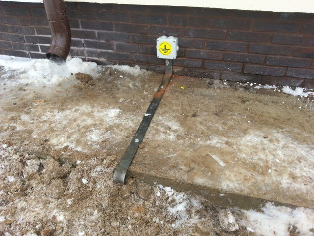
Entering the house
The busbar from the circuit is introduced into the entrance electric panel. A hole is drilled at the end for a bolted connection. Here you connect the corresponding conductor of the cable. In a TN-C-S system the busbar is connected to a splitter busbar.
Checking and Inspection
The control is carried out by measuring the electrical resistance of the entire circuit. It must not exceed the standard values
Often a simple way of testing is used. An incandescent lamp of 100-150 W is attached - one end to the phase, the other to the ground. Its clear glow indicates a quality installation. If it burns dimly, it is necessary to check the quality of the joints. If the lamp does not glow, the assembly is not done properly.
Prefabricated grounding kits for private homes
Self-assembly can significantly reduce the cost of the grounding system. However, ready-made kits allow you to accelerate the work and increase the reliability of the circuit. It is possible to allocate such models:
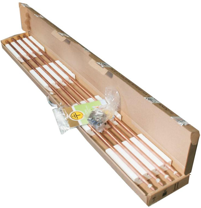
- ZandZ - Circuit with one or more electrodes of stainless steel. Allowed burial - up to 10 m. The price depends on the length of the pins. The average price of a set with five-meter electrodes - 23500 rubles.
- Galmar - has electrodes up to 30 m in length. The average price is 41,000 rubles.
- Elmast. This system is made in Russia and is adapted to Russian operating conditions. Price - from 8000 rubles.
Important! There are many models on the Russian market, which allows you to make the best choice. The depth of hammering their electrodes ranges from 5 to 40 m. The price range - 6000-28000 rubles.
Features of the schemes of grounding of 220 V and 380 V
Grounding schemes at the entry of networks to 220 and 380 V has certain differences. The external circuit of such systems is absolutely the same. The difference lies in the wiring and entry into the house. In the case of a 220 V network, a two-wire line is introduced. One core is split into "neutral" and "ground", and the other is installed on insulators.
In the case of a 380 V network, a four-wire line is most often suitable. One conductor is split in the same way as in the previous case, and the other 3 conductors are mounted on insulators and insulated from each other. Phase conductors and "neutral" are passed through a RCD and a residual current circuit breaker.
Common installation mistakes
Experts note that the following mistakes are most often made during independent installation:
- Trying to protect the electrodes from corrosion by painting. This method is inadmissible, as it prevents overflow into the ground.
- Connecting the steel metal bonding to the pins with bolts. Corrosion will break the contact between the elements fairly quickly.
- Excessive distance of the circuit from the house, which greatly increases the resistance of the system.
- The use of too thin a profile for the electrodes. After a short period of time, corrosion causes a dramatic increase in metal resistance.
- Contact of copper and aluminum conductors. In this case the connection deteriorates due to contact corrosion.
If defects in the design are detected, they must be corrected immediately. An excessive increase in electrical resistance or a disturbance in circuit continuity will disrupt the grounding operation. The circuit will not be able to guarantee safety.
A ground loop is essential for a private home. This design will ensure the electrical safety of the occupants and eliminate tragic accidents. However, it should be remembered that the effectiveness of grounding depends on the correct calculations, the choice of scheme and the conduct of installation. If there is any doubt in your own abilities, it is better to use a ready-made kit.
Related articles: