Modulation is a non-linear electrical process in which the parameters of one signal (carrier) are changed by another signal (modulating, information). Frequency, amplitude, and phase modulation are widely used in communication engineering. In power electronics and microprocessor technology pulse-width modulation is widespread.
Contents
What is PWM (pulse-width modulation)
In pulse-width modulation the amplitude, frequency and phase of the original signal remain unchanged. Under the influence of the information signal is subject to change the duration (width) of the rectangular pulse. In English technical literature it is denoted by the abbreviation PWM - pulse-width modulation.
Working principle of PWM
A pulse-width-modulated signal is formed in two ways:
- analog;
- digital.
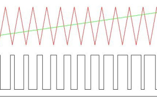
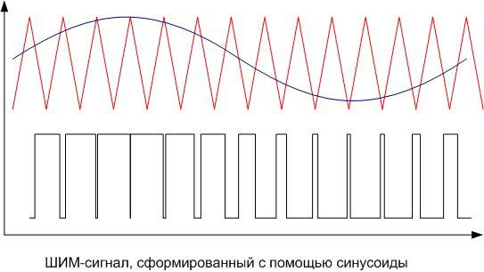
The analog PWM signal generation method uses a sawtooth or triangular carrier signal at the inverting input of the comparatorand the information signal is sent to the non-inverting input of the comparator. If the instantaneous level of the carrier is higher than the modulating signal, the comparator output is zero, if lower - one. The output is a discrete signal with a frequency corresponding to the frequency of the carrier triangle or sawtooth, and a pulse length proportional to the modulating voltage level.
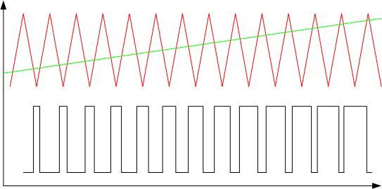
As an example, the pulse width modulation of a triangular signal by a linear-increasing signal is shown. The duration of the output pulses is proportional to the level of the output signal.
Analog PWM controllers are also available as off-the-shelf integrated circuits that contain a comparator and carrier generation circuitry. There are inputs for connecting external frequency encoder elements and supplying an information signal. From the output, a signal is taken that controls powerful external switches. There are also inputs for feedback - they are needed to maintain the set regulation parameters. This is, for example, the TL494 chip. For cases where the consumer power is relatively low, PWM controllers with built-in keys are available. For currents up to 3 amps the internal switch of the LM2596 chip is designed.
The digital method is performed using specialized chips or microprocessors. The pulse length is controlled by an internal program. Many microcontrollers, including popular PIC and AVR, have a module onboard for hardware PWM implementation. To get PWM signal it is necessary to activate the module and set its operating parameters. If there is no such a module, you can organize PWM by a purely software method, it is not difficult. This method gives more possibilities and gives more freedom due to flexible use of outputs, but involves more resources of the controller.
PWM signal characteristics
The important characteristics of the PWM signal are:
- amplitude (U);
- frequency (f);
- Duty cycle (S) or fill factor D.
The amplitude in volts is set depending on the load. It must provide the nominal supply voltage of the consumer.
The frequency of the pulse-width modulated signal is chosen from the following considerations:
- The higher the frequency, the greater the regulation accuracy.
- The frequency must not be lower than the response time of the device, which is controlled by PWM, otherwise there will be noticeable pulsations of the regulated parameter.
- The higher the frequency, the higher the switching losses. This is due to the fact that the switching time of the key is finite. In the latched state, the entire supply voltage falls on the key element, but there is almost no current. In the open state, the full load current flows through the key, but the voltage drop is small because the pass-through resistance is a few ohms. In both cases, the power dissipation is negligible. The transition from one state to the other is fast, but not instantaneous. During the open-close process a large voltage drops on the partially open element and at the same time a significant current flows through it. At this time the power dissipation reaches high values. This period is short, the key does not have time to warm up considerably. But as the frequency increases, there are more such time intervals per unit time and the heat loss increases. Therefore, it is important to use fast-acting elements for the construction of keys.
- When controlling of a motor the frequency has to be lead beyond the range audible to man - 25 kHz and above. Because at lower PWM frequencies, unpleasant whistling occurs.
These requirements are often in conflict with each other, so the choice of frequency in some cases is a search for a compromise.
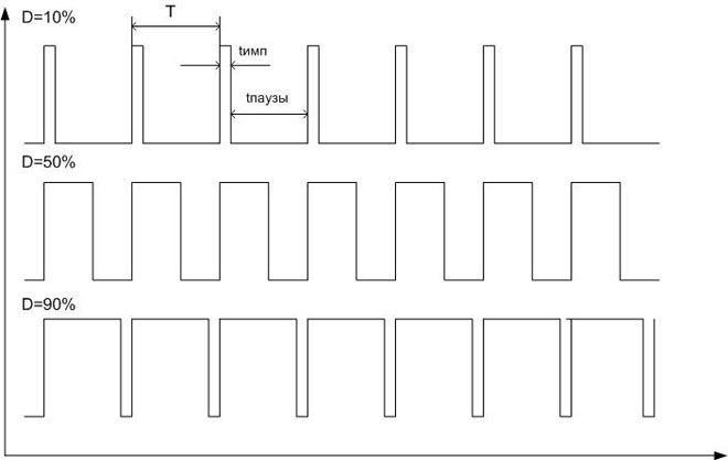
The magnitude of modulation is characterized by the duty cycle. Since the pulse repetition rate is constant, the period duration is also constant (T=1/f). A period consists of a pulse and a pause, which have a duration, respectively, timp and tpause, where timp+tpause=Т. Ratio is the ratio of pulse duration to period - S=timp/T. But in practice it turned out more convenient to use the inverse value - the fill factor: D=1/S=T/timp.. It is even more convenient to express the fill factor as a percentage.
What is the difference between PWM and PWM
In foreign technical literature, there is no distinction between pulse-width modulation and pulse-width control (PWM). Russian experts are trying to distinguish between these concepts. In fact, PWM is a type of modulation, that is, a change in the carrier signal under the action of another, modulating signal. The carrier signal acts as a carrier of information, and the modulating signal sets this information. And pulse width control is the regulation of the load mode by means of PWM.
Reasons and applications for PWM
The principle of pulse-width modulation is used in Speed controllers for powerful induction motors. In this case, a modulating signal of adjustable frequency (single-phase or three-phase) is formed by a low-power sine wave generator and superimposed on the carrier in an analog way. The output is a PWM signal, which is fed to the power demand keys. Then you can pass the resulting sequence of pulses through a low-pass filter, such as a simple RC-chain, and isolate the original sinusoid. Or you can do without it - filtering will happen naturally due to the inertia of the motor. Obviously, the higher the carrier frequency, the more the shape of the output signal is close to the original sinusoid.
A natural question arises - why can't you amplify the oscillator signal at once, for example, using high power transistors? Because the regulating element, operating in linear mode, will redistribute power between the load and the switch. This means a lot of power is wasted on the key element. If, on the other hand, a powerful regulating element works in key mode (trinistors, triacs, RGBT transistors), the power is distributed over time. The losses will be much lower and the efficiency will be much higher.
In digital technology, there is no special alternative to pulse width control. The signal amplitude is constant there, and the only way to change the voltage and current is to modulate the pulse width carrier and then average it. Therefore, PWM is used to regulate voltage and current at those objects that can average the pulse signal. Averaging occurs in different ways:
- By load inertia. Thus, the thermal inertia of thermoelectric heaters and incandescent lamps allows the control objects not to cool down noticeably in the pauses between pulses.
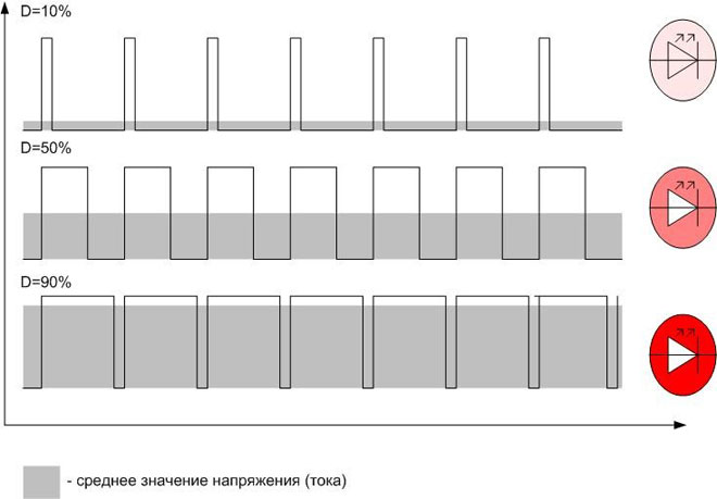
- Due to the inertia of perception. The LED has time to fade from pulse to pulse, but the human eye does not notice this and perceives it as a constant glow with varying intensity. The brightness control of LED monitors is based on this principle. But imperceptible blinking with a frequency of several hundred hertz is still present and causes eye fatigue.
- Due to the mechanical inertia. This property is used to control DC collector motors. If the control frequency is properly selected, the motor does not have time to stall in the dead time pauses.
Therefore, PWM is used where the average value of voltage or current plays a decisive role. In addition to the mentioned common cases, the PWM method regulates the average current in welding machines and battery chargers, etc.
If natural averaging is not possible, in many cases this role can be assumed by the already mentioned low-pass filter (LPF) in the form of RC-chain. For practical purposes this is enough, but it should be understood that it is impossible to isolate the original signal from the PWM with an LPF without distortion. After all, the PWM spectrum contains an infinitely large number of harmonics, which will inevitably get into the filter bandwidth. Therefore, do not have any illusions about the shape of the restored sinusoid.
PWM control of an RGB LED is very effective and efficient. This device has three p-n junctions - red, blue, green. By changing the brightness of each channel separately, you can get almost any color of LED glow (except pure white). The possibilities to create light effects with PWM are endless.
The most common application of digital pulse width modulated signal is to control the average current or voltage flowing through the load. But non-standard use of this type of modulation is also possible. It all depends on the designer's imagination.
Related articles: