A transformer is an electronic device capable of changing operating quantities, measured by the transformation ratio, k. This number indicates the change, scaling of some parameter, such as voltage, current, resistance or power.
Contents
What is the transformation ratio
A transformer does not change one parameter into another, but works with their values. Nevertheless, it is called a transformer. Depending on the connection of the primary winding to the power supply, the purpose of the device changes.
In the home, these devices are widespread. Their purpose is to supply the home device with power that corresponds to the nominal value specified in the passport of this device. For example, the mains voltage is 220 volts, the phone battery is charged from a 6 volt power supply. Therefore, it is necessary to reduce the mains voltage by 220:6 = 36.7 times, this value is called the transformation ratio.
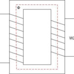
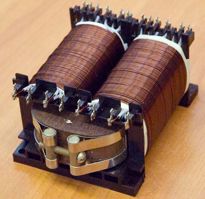
In order to accurately calculate this figure, it is necessary to remember the structure of the transformer itself. Any such device has a core made of a special alloy, and at least 2 coils:
- primary;
- secondary.
The primary coil is connected to the power supply, the secondary coil is connected to the load, there can be 1 or more. A winding is a coil consisting of electrical insulating wire wound on a frame, or without a frame. A complete turn of wire is called a coil. The first and second coils are mounted on a core, with which energy is transferred between the windings.
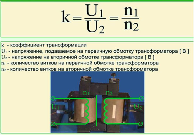
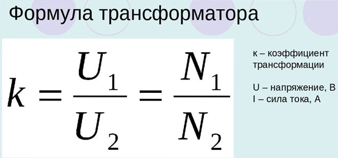
The transformation ratio of a transformer
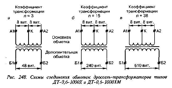
A special formula determines the number of wires in the winding, taking into account all the features of the core used. Therefore, in different devices, the number of turns in the primary coils will be different, despite being connected to the same power source. The turns are calculated relative to the voltage, if several loads with different supply voltages are to be connected to the transformer, the number of secondary windings will correspond to the number of loads to be connected.
Knowing the number of turns of wire in the primary and secondary windings, you can calculate the k of the device. According to the definition from GOST 17596-72 "The transformation ratio - The ratio of the number of turns of the secondary winding to the number of turns of the primary winding, or the ratio of the secondary voltage to the primary voltage in no-load mode without regard to the voltage drop on the transformer." If this coefficient k is greater than 1, then the device is a step-down, if less - a step-up. There is no such distinction in GOST, so the higher number is divided by the lower number and k is always greater than 1.
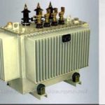
In the power supply, converters help to reduce losses in power transmission. To do this, the voltage generated by the power plant is increased to several hundred thousand volts. Then the voltage is lowered to the required value using the same devices.
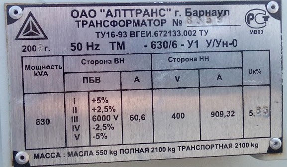
Transformers with voltage regulators are installed in traction substations that supply the industrial and residential complexes with power. From the secondary coil, additional leads are taken away, the connection to which allows the voltage to be changed in a small range. This is done by bolted connection or by a knob. In this case, the transformation ratio of the power transformer is specified in its data sheet.
Definition and formula for transformer transformation ratio
It turns out that the coefficient is a constant value that shows the scaling of electrical parameters, it depends entirely on the design features of the device. For different parameters, the calculation of k is done differently. There are the following categories of transformers:
- by voltage;
- by current;
- by resistance.
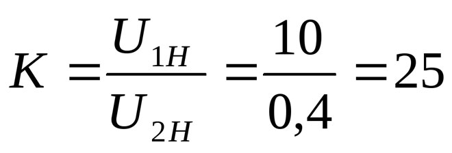
Before determining the coefficient it is necessary to measure the voltage on the coils. GOST states that such measurement should be made at idle. This is when no load is connected to the inverter, the readings can be shown on the nameplate of this device.
Then the readings of the primary winding divided by the readings of the secondary winding, this will be the coefficient. If the number of turns in each coil is known, the number of turns in the primary winding is divided by the number of turns in the secondary winding. In this calculation, the active resistance of the coils is neglected. If there are several secondary windings, a different k is found for each winding.
Current transformers have their own peculiarity, their primary winding is connected in series with the load. Primary and secondary currents are measured before calculating the k-value. The primary current is decomposed into the secondary current. If there are data on the number of turns, it is possible to calculate k by dividing the number of turns of the secondary winding wire by the number of turns of the primary winding wire.
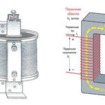
When calculating the coefficient for resistance transformer, also called matching transformer, first find the input and output resistance. To do this, calculate the power, which is equal to the product of voltage and current. Then the power is divided by the square of the voltage to get the resistance. Fracturing the input resistance of the transformer and load with respect to its primary circuit and the input resistance of the load in the secondary circuit will give k of the device.
There is another way to calculate this. You need to find the k coefficient of voltage and square it, the result will be similar.
Different kinds of transformers and their coefficients
Although structurally converters do not differ much from each other, their purpose is quite extensive. There are the following types of transformers, in addition to those mentioned above:
- power transformer;
- autotransformer;
- pulse
- welding
- isolating
- matching;
- pic-transformer;
- double choke;
- transfluctor;
- rotating;
- air and oil;
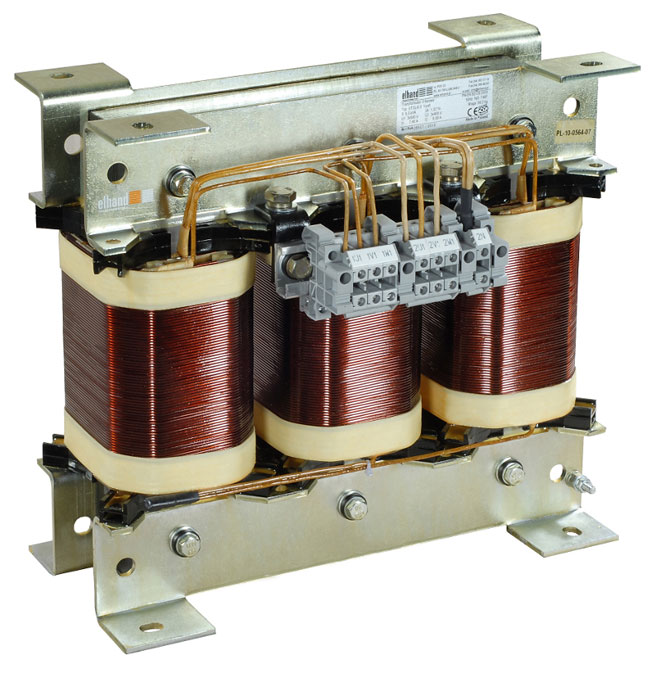
- three-phase.
A feature of the autotransformer is the absence of galvanic isolation, the primary and secondary windings are made with one wire, with the secondary being part of the primary. The pulsed one scales short pulse signals of rectangular shape. The welding one operates in short-circuit mode. Separators are used where special electrical safety is needed: wet rooms, rooms with a lot of metal products and the like. Their k is mostly equal to 1.
A pickup transformer converts a sinusoidal voltage to a pulsed voltage. A dual choke is two twin coils, but refers to transformers by their design features. The transfluctor contains a core made of a magnetic wire, which has a large value of residual magnetization, which allows it to be used as a memory. The rotating one transmits signals to rotating objects.
Air and oil transformers differ in the way they are cooled. The oil ones are used for scaling high power. Three-phase are used in a three-phase circuit.
For more information on the current transformer transformation ratio, see the table.
| Nominal secondary load, V | 3 | 5 | 10 | 15 | 20 | 30 | 40 | 50 | 60 | 75 | 100 |
|---|---|---|---|---|---|---|---|---|---|---|---|
| Ratio, n | Nominal multiplicity limit | ||||||||||
| 3000/5 | 37 | 31 | 25 | 20 | 17 | 13 | 11 | 9 | 8 | 6 | 5 |
| 4000/5 | 38 | 32 | 26 | 22 | 20 | 15 | 13 | 11 | 10 | 8 | 6 |
| 5000/5 | 38 | 29 | 25 | 22 | 20 | 16 | 14 | 12 | 11 | 10 | 8 |
| 6000/5 | 39 | 28 | 25 | 22 | 20 | 16 | 15 | 13 | 12 | 10 | 8 |
| 8000/5 | 38 | 21 | 20 | 19 | 18 | 14 | 14 | 13 | 12 | 11 | 9 |
| 10000/5 | 37 | 16 | 15 | 15 | 14 | 12 | 12 | 12 | 11 | 10 | 9 |
| 12000/5 | 39 | 20 | 19 | 18 | 18 | 12 | 15 | 14 | 13 | 12 | 11 |
| 14000/5 | 38 | 15 | 15 | 14 | 14 | 12 | 13 | 12 | 12 | 11 | 10 |
| 16000/5 | 36 | 15 | 14 | 13 | 13 | 12 | 10 | 10 | 10 | 9 | 9 |
| 18000/5 | 41 | 16 | 16 | 15 | 15 | 12 | 14 | 14 | 13 | 12 | 12 |
Almost all the devices listed have a core to transmit magnetic flux. The flux appears due to the movement of electrons in each of the coils of the winding, and the currents must not be zero. The current transformation ratio also depends on the type of core:
- core;
- armored.
In an armored core, magnetic fields have a greater effect on scaling.
Related articles: