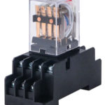
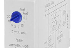
For comfortable living today, many homes and apartments use automated systems with electronics. You may have already heard about the pass-through and marching switches: they help to assemble a lighting control scheme in several places. Despite the practicality of the principles of such a system with the wiring, as well as its connection is not too simple. Nevertheless, there is a simpler option - the use of an interesting bistable device, which is otherwise called a pulse relay.
Contents
Purpose and where it is used
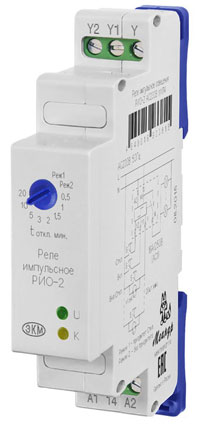
This switch is designed to turn the load on or off when a signal is applied to the contacts. The relay is called bistable because it switches on and off precisely when the signal is applied to the control input. And the relay remains in this position after the input signal ends.
It is noteworthy that even after disconnection from the mains the impulse relay "remembers" the last position of the contacts, and when switched on it resumes the state it had before it was switched off.
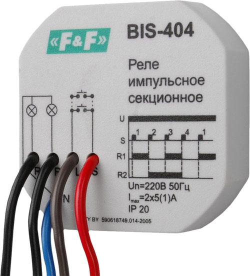
In everyday life, this device is very often used because of its convenience, as the light can be controlled from at least two points. For example, the light was turned on in the bedroom, and off - in the corridor before leaving the apartment. Such a system will come in handy when the rooms are very long and large in size.
WARNING! In addition to comfort, the impulse relay offers a solution also for such tasks as protection and alarm. For example, in industrial firms, where high electrical power is required, the device ensures the safety of the operator because it operates from a low voltage and can be controlled remotely.
Operating principle and appearance
Generally speaking, a relay is an electrical mechanism that closes or breaks an electrical circuit. Its operation is based on the electrical or other parameters that act on it.
When selecting the mode of operation of the relay, you should be guided by the frequency of switching, the magnitude of current, as well as the nature of the tested loads.
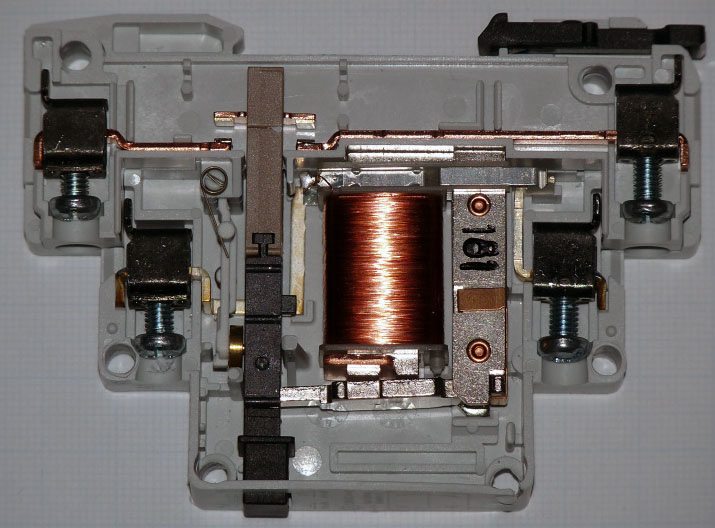
The design consists of the following components:
- Coil.
The coil is a copper wire that is wound on a nonmagnetic material; it can be in fabric insulation or covered with a special varnish that does not let electricity pass through; - The core.
It contains iron and is actuated by the passage of current through the coils of the coil; - A movable armature.
This armature is a plate attached to the armature, it acts on the closing contacts; - A contact system.
It is the switch for the state of the circuit.
The relay is based on the electromagnetic force generated in the coil core when current is passed through it.
The coil is a retracting device in which the core is connected to a moving armature. It actuates the power contacts. And a resistor can additionally be connected to the coil to increase the accuracy of actuation.
Variety of impulse relays
IMPORTANT! A bistable relay is a relay that can be in two fixed (stable) states. Because of the nature of this device, it is sometimes called a "blocking" relay, because it blocks the network in one state.
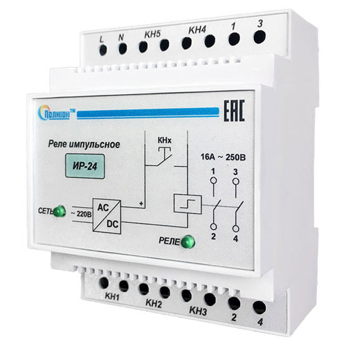
There are big differences between some relays, so they can be divided mainly into 2 categories:
- electromechanical relays;
- Electronic impulse relays.
Electromechanical
This type of device consumes electricity only at the moment of actuation. The locking mechanism provides high reliability and saves electricity. The system works quite well: what is meant is protection against fluctuations in the mains, which lead to false alarms.
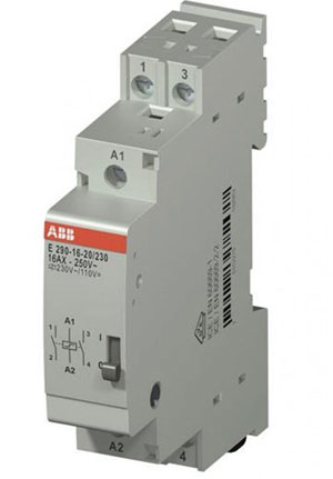
The design is based on a coil, contacts, and a mechanism with buttons for switching on and off.
Electromechanical type relays are considered more reliable and convenient to use because they are not afraid of interference. Plus, they don't have high requirements for installation location.
Electronic
Electronic impulse relays have a characteristic feature: they use microcontrollers. Thanks to this, they have advanced functionality. For example, such devices allow you to add a timer. Other additional functions help in building complex lighting systems.
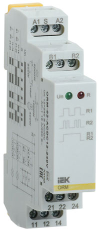
The design is based on: an electromagnetic coil, microcontrollers, semiconductor keys.
Electronic relays are more popular than other types because of the functionality and variety that can be added to them: you can create products for lighting of any complexity. It is also possible to select them for any voltage - 12 volts, 24, 130, 220. Depending on the installation such relays can be DIN-standard (for electric boards) and conventional (with other ways of mounting).
Main technical characteristics
Relays can be classified according to the following parameters, depending on the purpose and application:
- return coefficient is the ratio of armature output current to retraction current;
- Output current is the maximum coil current at armature output;
- retract current is the minimum current in the coil when the armature returns to its home position;
- set point - the value of triggering within the limits that are set in the relay;
- Triggering value - the input signal to which the device responds automatically;
- nominal values - these are the voltage, current and other quantities that underlie the operation of the relay.
Electromagnetic relays can also be divided by time of operation. Such a device has such a parameter as a long delay - more than 1 second, with the possibility of setting. Then there are delayed - 0.15 seconds, normal - 0.05 seconds, fastest inertia-free relays - less than 0.001 seconds.
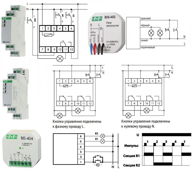
Other pulse relay specifications may include:
- maximum load of incandescent lamps;
- number and type of contacts;
- operating temperature range;
- relative humidity;
- etc.
Wiring Diagrams
Impulse relay is very often used with the connection of several switches with spring return button. They should be connected in parallel to each other according to all requirements.
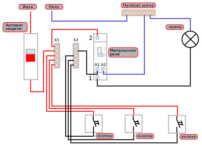
To organize a lighting control scheme, you should connect the power wire to the bistable relay. And the switches are connected to each other by means of wiring. This makes it possible to de-energize the entire network later, using just one switch.
This option is popular because it simplifies installation. It is necessary to calculate the characteristics accurately: for example, the support of the LED button illumination, so that the network fully functions.
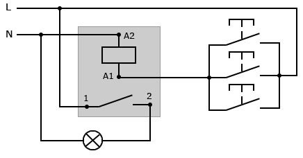
To be more convenient, you can check the markings. Manufacturers use designations such as:
- A1-A2 - coil contacts;
- 1-2 (or other numbers) - the number of contacts that close or open when the bistable relay operates;
- ON-OFF - marking of contacts, which switch the relay in off or on state (it is used when installing the central control).
TIP! As a rule, a 220 volt relay is used for connection to a power panel. In this case, cables are connected to the contacts, and further control is done through a pulse relay. And the individual switches in the whole lighting system are connected by wires.
Advantages and disadvantages
The basic types of relays have many advantages over solid-state switches, such as:
- relatively low cost (due to inexpensive components);
- there is a strong insulation between the coil and the contact group;
- are not subject to the harmful influence of overvoltage, lightning interference, switching of powerful electrical installations;
- there is a control of lines with loads up to 0,4 kV (with small volume of the device).
An additional plus is that there is no cooling problem and harmless to the atmosphere. For example, a short circuit with a current of 10 A in the relay distributes less than 0.5 watts across the coil. Compared to electronic counterparts, this value is higher than 15 watts.
Disadvantages of the impulse relay:
- Wear and tear, and problems switching inductive loads and high voltages (if the current is constant);
- Radio interference occurs when switching the circuit on and off, so shielding is required;
- relatively long actuation time.
A serious disadvantage can be considered continuous wear and tear during switching (deformation of springs, oxidation of contacts, for example).
However, it is worth specifying that when using exactly electronic relays, there are advantages such as: safety, good connection speed, availability in the market, silent operation, extended functionality. And among the disadvantages: overheating when switching large currents, malfunction during power failures, resistance in the closed position, etc.
Nevertheless, electronic relays are developing quite steadily and quickly. They are popular because of their functionality, which can be extended relatively easily.
Conclusion
Modern lighting and electrification systems make very extensive use of the pulse relay. The market demands on the manufacturers of such relays are getting higher and higher, which gives rise to continuous development in this area.
Most users require extended functionality and flexibility in lighting control. Therefore, demand drives supply, as this technology is very much in demand today.
Related articles:
