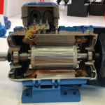
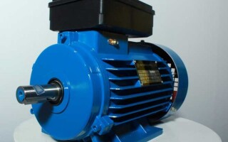
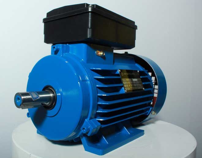
Single-phase electric motor functioning is based on using alternating electric current through connection to single-phase networks. The voltage in such a network must correspond to the standard value of 220 volts, the frequency - 50 Hz. This type of motor is mainly used in household appliances, pumps, small fans, etc.
The power of single-phase motors is also sufficient for electrifying private houses, garages or summer cottages. In these conditions, a single-phase electric network with a voltage of 220 V is used, which imposes some requirements on the process of connecting the motor. Here, a special scheme is used, which involves the use of a device with a starting winding.
Contents
Wiring diagram for single-phase motors with capacitor
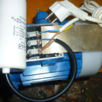
Single-phase 220v electric motors are connected to the network using a capacitor. This is due to some design features of the unit. For example, an alternating current winding in the motor stator produces a magnetic field whose pulses are compensated only by reversing polarity at a frequency of 50 Hz. Despite the characteristic sound of the single-phase motor, it does not rotate the rotor. The torque is created by using additional starting windings.
To understand how to connect a single-phase electric motor through a capacitor, it is sufficient to consider 3 working schemes using a capacitor:
- starting capacitor;
- running;
- running and starting (combined).
Each of the above connection schemes is suitable for use in the operation of 220v asynchronous single-phase electric motors. However, each option has its own strengths and weaknesses, so they deserve a more detailed introduction.
The idea of using a starting capacitor is to include it in the circuit only at the time of starting the motor. For this purpose, the circuit provides a special button designed to open the contacts after the rotor reaches a predetermined speed level. Its further rotation takes place under the influence of inertial force.
The magnetic field of the main winding of a single-phase motor with a capacitor maintains the rotary motion for a long period of time. A relay specially provided for this purpose can perform the function of a switch.
The capacitor single-phase motor connection diagram has a spring-loaded push button that opens the contacts when they are opened. This approach makes it possible to reduce the number of wires used (a thinner starter winding can be used). In order to avoid short circuits between coils, it is recommended to use a thermal relay.
When critical high temperatures are reached, this element deactivates the additional winding. The same function can be performed by a centrifugal switch which is installed to open the contacts in cases where the permissible speed values are exceeded.
Appropriate circuits are developed for automatic speed control and motor overload protection, and various correction components are incorporated into the design of the units. The centrifugal switch can be mounted directly on the rotor shaft or on components connected to it (by direct or gear connection).
The centrifugal force acting on the weight contributes to the tensioning of the spring connected to the contact plate. If the speed reaches a predetermined value, the contacts close and the current flow to the motor is stopped. The signal can be transmitted to another control mechanism.
There are circuit variants in which a centrifugal switch and a thermal relay are included in one component. Such a solution makes it possible to deactivate the motor by means of a thermal component (in case critical temperatures are reached) or by the sliding element of the centrifugal switch.
If the motor is connected via a capacitor, the magnetic field lines in the auxiliary winding are often distorted. This entails an increase in power losses, a general decrease in the performance of the unit. However, good starting performance is retained.
The use of a running capacitor in the connection scheme of a single-phase motor with a starting winding implies a number of distinctive features. Thus, after start-up the capacitor is not disconnected, the rotation of the rotor is carried out by impulse action from the secondary winding. This significantly increases the power of the motor, and the competent selection of the capacitor capacity allows to optimize the shape of the electromagnetic field. However, the motor start-up becomes longer.
The selection of a capacitor of suitable capacity is made taking into account the current loads, which allows the electromagnetic field to be optimized. If the nominal values change, there will be fluctuations in all other parameters. The use of several capacitors with different capacitive characteristics makes it possible to stabilize the shape of magnetic field lines. This approach allows to optimize the performance of the system, but involves some complexities in the installation and operation processes.
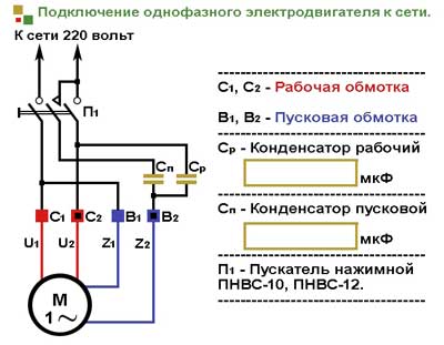
Combined connection scheme of single-phase motor with starting winding is designed to use two capacitors - working and starting one. This is the optimum solution for achieving average performance.
Calculating the capacitance of a motor capacitor
There is a complicated formula to calculate the exact capacitor capacity required. However, many years of professional experience show that it is sufficient to adhere to the following recommendations:
- 0.8 μF operating capacitor per 1 kW of motor power is necessary;
- The starting winding requires this value to be 2 or 3 times higher.
The operating voltage for them should be 1.5 times higher than the mains voltage (in our case 220 V). To simplify the starting process, it is better to install a capacitor labeled "Starting" or "Start" in the starting circuit. Although the use of standard capacitors is allowed.
Reversal of motor direction
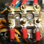
It is possible that once connected, single-phase motors will rotate in the opposite direction to the desired direction. This is not difficult to correct. During the circuit assembly one wire was brought out as a common, another wire was fed to the button. In order to change the rotating magnetic direction of the electric motor, these 2 wires must be swapped.
Related articles: