Electric appliances should work without faults if the electrical circuit complies with all norms and standards. But in the power supply lines there are changes that, over time, affect the technical parameters of the network. In this regard, it is necessary to carry out periodic measurements and preventive maintenance of the power supply. As a rule, check the functionality of the circuit breakers, RCDSas well as the parameters of the phase-zero loop. The following describes the details of the measurements, what devices to use and how to analyze the results.
Contents
What is meant by the term phase-zero loop?
According to the rules of the Electrical Installations Code in power substations with voltages up to 1000 V with a deaf-earthed neutral point The resistance of the phase-ground loop must be measured at regular intervals.
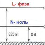
A phase-zero loop is formed if you connect the phase wire to the neutral or protective conductor. This creates a loop with its own resistance through which the electric current travels. In practice, the number of elements in the loop can be much greater and include circuit breakers, terminals and other connecting devices. If necessary, it is possible to calculate the resistance manually, but the method has several disadvantages:
- it is difficult to take into account the parameters of all switching elements, including circuit breakers, circuit breakers, and circuit breakers, which may have changed during the operation of the network;
- it is impossible to calculate the impact of an emergency situation on the resistance.
The most reliable way is to measure the value with a certified device, which takes into account all the errors and shows the correct result. But before starting the measurement it is necessary to do some preparatory work.
Why check the phase-zero loop resistance
This check is important for preventative purposes and to make sure the protective devices, including circuit breakers, RCDs, and circuit breakers, residual current circuit breakers (RCDs) and automatic circuit breakers (AC/DCs). The result of a phase-zero loop measurement is the practical determination of the resistance of the power line to the circuit breaker. Based on this, the short-circuit current is calculated (mains voltage divided by this resistance). Then we conclude: whether the circuit breaker that protects this line will be able to disconnect at short circuit.
For example, if the circuit breaker C16 is installed on the line, the maximum short-circuit current may be up to 160 A, after which it will disconnect the line. Suppose the measurement results in a phase-zero loop resistance value of 0.7 ohms in a 220V network, so the current is 220 / 0.7 = 314 A. This current is more than 160 A, so the circuit breaker will switch off before the wires start to burn, and therefore we consider that this line corresponds to the norm.
Important! High resistance is the cause of false tripping of protection, heating of cables and fire.
This can be caused by external factors, which are difficult to influence, or by a mismatch between the rating of the protection and the operating parameters. But in most cases, it is due to internal problems. The most common causes of faulty tripping of circuit breakers are:
- Loose contact on the terminals;
- mismatching current to the characteristics of the wire;
- Reduction of wire resistance due to obsolescence.
Using measurements allows you to get detailed data about the network parameters, including the transient resistance, as well as the impact of loop elements on its performance. In other words, the phase-zero loop is used to prevent protective devices and correctly restore their functions.
Knowing the parameters of the circuit breaker of a particular line, after measuring, you can say with certainty Whether it will trip in the event of a short-circuit or the wires will burn out.

Measuring intervals
Reliable operation of the power grid and all household appliances is possible only if all parameters meet the standards. A periodic check of the phase-ground loop is required to ensure proper performance. Measurement is performed in the following situations:
- After equipment commissioning, repairs, upgrades, or mains preventive maintenance.
- At the request of the utility company.
- At the request of the power consumer.
Information! Frequency of inspection in aggressive conditions - at least once every 2 years.
The main purpose of the measurements is to protect electrical equipment as well as power lines from heavy loads. As a result of the increase in resistance, the cable begins to get very hot, which leads to overheating, tripping of circuit breakers and fires. The value is affected by many factors, including the aggressiveness of the environment, temperature, humidity, etc.
What kind of gauges are used?
Special certified devices are used to measure phase parameters. The devices differ in measurement methods, as well as design features. The following measuring devices are the most popular among electricians:
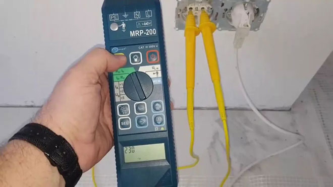
- М-417. Proven by experience and time device designed to measure resistance without disconnecting the power supply. Of the features stand out the ease of use, size and digital display. The device is used in all AC networks with voltage of 380V and permissible deviations of 10%. M-417 automatically opens circuit for an interval of up to 0.3 seconds for measurements.
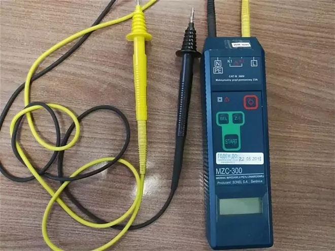
- MZC-300. Modern equipment for checking the condition of switching elements. Methods of measurements are described in GOST 50571.16-99 and consists in simulating a short circuit. The device works in networks with voltages of 180-250V and registers the result in 0.3 seconds. For greater reliability there are indicators of low or high voltage, as well as protection against overheating.
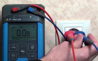
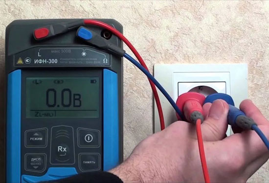
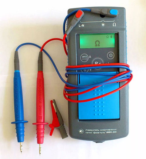
- IFN-200. Microprocessor-controlled device for measuring phase-zero loop resistance without removing power. Reliable device guarantees the accuracy of the result with an error of up to 3%. It is used in networks with voltages from 30V to 280V. Additional advantages include short circuit current, voltage and phase angle measurements. Also INF-200 device remembers the results of the last 35 measurements.
Important! The accuracy of the measurement results depends not only on the quality of the instrument, but also on following the rules for the chosen technique.
How the loop resistance of a phase-zero loop is measured
Measuring loop characteristics depends on the chosen technique and instrument. There are three basic methods:
- Short circuit. The device is connected to the working circuit at the furthest point from the input panel. The device makes a short circuit and measures short circuit current, time of operation of circuit breakers. On the basis of the data the parameters are automatically calculated.
- Voltage drop. For this method it is necessary to disconnect the mains load and connect a reference resistor. The test is carried out with a device that processes the results. The method is considered one of the safest.
- Ammeter-voltmeter method. A rather complicated variant, which is carried out with the voltage removed, and a step-down transformer is used. By shorting the phase wire to the electrical installation, measure the parameters and make calculations of the characteristics according to the formulas.
Methods of measurement
The simplest technique is considered the voltage drop in the network. To do this, the load is connected to the power line and the necessary parameters are measured. This is a simple and safe method that does not require special skills, The measurement can be carried out:
- between one of the phases and the neutral wire;
- Between a phase and the PE wire;
- Between the phase and protective earth.
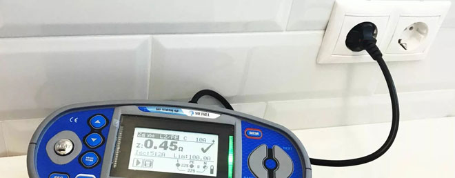
After the device is connected it starts to measure the resistance. The required direct parameter or the indirect results are displayed on the screen. They must be saved for later analysis. It is worth bearing in mind that the measuring devices will cause the RCD to trip, so it is necessary to shunt them before testing.
Note! The load is connected to the most distant point (the socketpoint (socket) of the power supply.
Analysis of measurement results and conclusions
The resulting parameters are used to analyze the characteristics of the network as well as its preventive maintenance. Based on the results, decisions are made to upgrade the transmission line or continue operation. Among the main features are the following:
- Determination of the safety of network operation and the reliability of protective devices. The technical serviceability of the wiring is checked and the possibility of further operation without interference.
- Finding problem areas for upgrading the power supply line to the premises.
- Determination of measures to upgrade the network for reliable operation of circuit breakers and other protective devices.
If the indicators are within normal limits and the short-circuit current does not exceed the cutoff values of circuit breakers, no additional measures are required. Otherwise, it is necessary to look for problematic places and eliminate them to ensure the operability of circuit breakers.
Measurement report form

The last step in measuring the phase-zero loop resistance is to record the readings. This is necessary in order to save the results and use them for comparison in the future. The record includes the date of the test, the result obtained, the instrument used, the type of tripping device, its measuring range and accuracy class.
At the end of the form a summary of the test results is written. If it is satisfactory, the conclusion indicates the possibility of further operation of the network without taking additional measures, and if not - a list of necessary actions to improve the indicator.
In conclusion, it is necessary to emphasize the importance of loop resistance measurements. Timely search for problematic areas of power lines allows preventive measures to be taken. This will not only secure the work with electrical appliances, but also increase the life of the network.
Related articles: