To control lighting there are a large number of ways, as, in fact, types of lighting devices. In this article, the devices for light control and variants of their installation and connection will be considered.

Contents
General principles for installing light switches
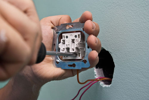
Installation of a simple lighting system and control devices is carried out during the repair work in the room. In the case of concealed wiring, before finishing work, the cable is laid in cut-outs and prepare places for the installation of switches. In this case, switching of switches, lights and supply lines are made in junction boxes. Such boxes can be located in special niches in the walls, hidden in the floor or behind the tension (suspended) ceiling.
In some cases, for example in wooden houses, the regulations prohibit the installation of concealed wiring, so in such areas installation is made openly after finishing the room (with the use of cable channels or special corrugated tubes).
The general principle of connecting switches in most cases is the same: the switch serves to break the phase on the line, and the zero wire directly to the lamp. Why phase and not zero? This requirement is explicitly stated in the PUE, which states that it must not be possible to break one neutral conductor without disconnecting the phase conductor. This is directly related to safety measures when operating lighting fixtures. There must be no voltage applied to the device when it is disconnected from the mains with a switch so that it can be safely repaired or the lamp changed.
Location of switchesThe lighting controls are selected based on the habits of future users and the configuration of the room. It is generally accepted to mount the switches at at a height of 90 cm from the floor. This is due to the fact that such a switch can be conveniently used by both a child and an adult.
When planning the installation of switches, it is best to make a scheme of connecting wires in junction boxes and a plan showing the location of lighting points and control devices, as well as to make a marking directly on the walls. This will help to avoid mistakes.
Diagrams for connecting switches and lamps of different types
The choice of wiring diagrams depends on the number of lighting devices and points to control their work. Below we will consider the most common of them.
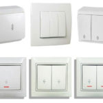
Single-key switch - the scheme for turning on one or more lamps at the same time
The most commonly used lighting connection option is Single light switch. It can be used to turn on and off a single light or several lights at the same time. It is mounted in a standard socket, in the case of flush mounting of electrical wiring. Or it can be laid overhead, when laying the cable in the open way. Installation of electrical wiring and connecting lights and switches is as follows:
- The power cable is laid from the electrical panel to the junction box above the location of the future switch;
- Prepares a place to install the switch and from it on the wall, strictly vertically, led a two-core wire to the junction box;
- From the junction box to the lighting fixtures (regardless of the number of lamps) the electric cable is led in a three-core (if the appliance must be grounded) or a two-core version (without grounding);
- Install the switch according to the diagram on the device;
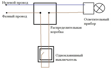
- In the junction box performs Connection of power linesThe power lines, lights and switches are connected to the junction box as shown in the diagram for the single push-button switch.
Scheme for the connection of such a switch for a single appliance is as follows.
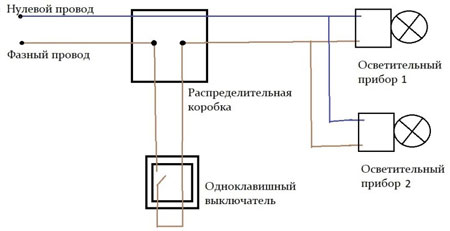
For several light fixtures that will be turned on at the same time, the scheme will change slightly.
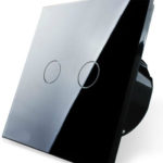
Two-button and three-button switch - separate switching of chandelier lamps or two independent lights
The connection of two- or three-way switches is made similarly to the single-way variant. The difference lies in the number of wires that are led to the switch and the wiring diagram in the junction box.
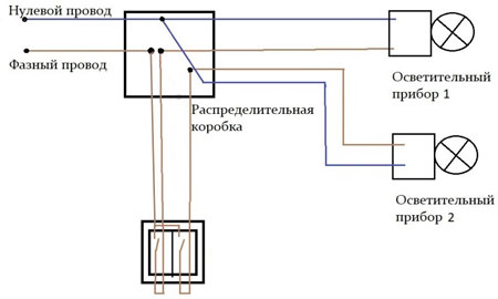
The two-way switch can be used to control two individual lights or the operation of a single chandelier with several lamps. For this purpose, one phase conductor is connected to the switch and two outgoing lines to the junction box. To the junction box bring phase and neutral conductors from the electrical panel, and from the lights zero and phase from each device.
Connection of a two-way switch and two light fixtures (or one chandelier with two operating modes) is as follows.
The installation of a circuit with three lights and a three-way switch is done in the same way, only one more outgoing wire from the switch and one more lighting device is added.
Connecting a chandelier with a fan
Connecting such a device as a chandelier with a fan can be done in two ways: with the simultaneous inclusion of the fan and lighting, as well as with the possibility of separate inclusion of each mode.
The first option involves installing the system with a single push-button switch, similar to the way you would install two lights to be switched on at the same time.
The second option requires the installation of three wires to a two-way switch (one key to turn on the light, the other key to turn on the fan) and three wires to the chandelier with the fan, similarly to the circuit for two independent lighting fixtures.
The choice of circuit depends on the desire of the user, as well as the type and number of wires laid to the switch and the point of suspension of the chandelier with a fan.
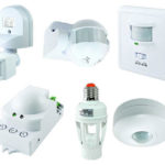
Proximity switches
This type of control device is used to automatically turn on lights. Proximity switches include a variety of control devices that are designed with sensors: a light sensor, motion sensor or timer.
Light sensor is used to turn on the light when insufficient light is detected. For example, this can be used to switch on street light at dusk.
Motion sensor The light can be switched on when motion is detected, for example when a person enters a room. They can have different versions: infrared, ultrasonic, radio wave or photoelectric. These devices allow you to save energy, are easy to install and easy to use.
The timer can be built in a separate control device or in the luminaire itself. It turns on or off the luminaire at the time set by the user.
Connecting a Loop Switch
There is also a way to control lighting from multiple points in a room. For example, a person entering a room turns the light on, while being in another part of the same room can turn the light off. This option is possible with the installation of feed-through circuit breakers. Their operating principle is based on "phase switching" in the switches themselves. When installing this type of control devices, the circuitry becomes more complicated and the cable consumption during installation increases, but this is justified in many situations. More details about the design, installation schemes and operating principle can be read in this article.
Related articles: