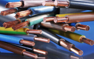
When repairing or designing electrical equipment you need to choose the right wires. You can use a special calculator or a reference book. But to do this, you need to know the parameters of the load and the peculiarities of cable installation.
Contents
Why calculate the cable cross section
The following requirements apply to electrical networks:
- safety;
- reliability;
- economy.
If the chosen cross-sectional area of the wire is small, the current loads on cables and wires will be high, which will lead to overheating. This can result in an emergency situation that will damage the entire electrical equipment and become dangerous to life and health.
If, on the other hand, wires with a large cross-sectional area are installed, safe application is assured. But from a financial point of view there will be overspending. The correct selection of the cross-sectional area of the wire is a guarantee of long-term safe operation and rational use of financial resources.
There is a separate chapter in PUE on proper conductor selection: "Chapter 1.3. Selection of conductors according to heating, economic current density and corona conditions".
The cross-sectional area of a cable is calculated according to its power and current. Let's look at examples. To determine what cross-section of the wire is needed for 5 kWYou will need to use the tables in "The Rules for Electrical Installations.Rules for Electrical Installations"). This guide is a regulatory document. It specifies that the cross-section of the cable is selected according to 4 criteria:
- Supply voltage (Single-phase or three-phase).
- Conductor material.
- Load current, measured in amperes (А), or power in kilowatts (kW).
- Cable location.
There is no value in the PUE. 5 kW, so we will have to choose the next higher value - 5,5 kW. For installation in an apartment today it is necessary to use copper wire. In most cases the installation is airborne, so a cross-section of 2.5 mm² is suitable from the reference tables. The maximum allowable current load will be 25 A.
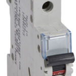
The aforementioned manual also specifies the current for which the input circuit breaker is designed (VA). According to "Rules for Electrical Installations"for a load of 5.5 kW, VA current must be 25 A. The document states that the rated current of the wire that goes to the house or apartment must be one step higher than that of the VA. In this case, after 25 amps is 35 amps. The last value should be taken as a calculation value. A current of 35 A corresponds to a cross-section of 4 mm² and a power of 7.7 kW. So, the selection of the cross-section of the copper wire according to the power is complete: 4 mm².
To find out what cross-section of copper wire is required for 10 kWagain we use the reference book. If you consider the case of open wiring, you must decide on the cable material and the supply voltage.
For exampleFor aluminum wire and 220 V voltage, the closest high power will be 13 kW, the corresponding cross-section - 10 mm²; for 380 V power will be 12 kW, and the cross-section - 4 mm².
Selection according to wattage
Before selecting a cable cross section by power, it is necessary to calculate its total value, to make a list of electrical appliances in the area to which the cable is laid. Each of the devices must be indicated on the power, next to it will be written the appropriate units of measurement: W or kW (1 kW = 1000 watts). Then you will need to add the power of all the equipment and will get the total.
If you choose a cable to connect a single appliance, then it is enough information only about its power consumption. You can pick up the cross-section of the wire by power in the tables of PUE.
Table 1. Selection of wire cross-section according to power for a cable with copper conductors
| Cross-section of conductive core, mm² | For cable with copper conductors | |||
| Voltage 220 V | Voltage 380 V | |||
| Current, A | Power, kW | Current, A | Power, kW | |
| 1,5 | 19 | 4,1 | 16 | 10,5 |
| 2,5 | 27 | 5,9 | 25 | 16,5 |
| 4 | 38 | 8,3 | 30 | 19,8 |
| 6 | 46 | 10,1 | 40 | 26,4 |
| 10 | 70 | 15,4 | 50 | 33 |
| 16 | 85 | 18,7 | 75 | 49,5 |
| 25 | 115 | 25,3 | 90 | 59,4 |
| 35 | 135 | 29,7 | 115 | 75.9 |
| 50 | 175 | 38.5 | 145 | 95,7 |
| 70 | 215 | 47,3 | 180 | 118,8 |
| 95 | 260 | 57,2 | 220 | 145,2 |
| 120 | 300 | 66 | 260 | 171,6 |
Table 2. Cross-sectional selection of wires according to power for cables with aluminum conductors
| Cross-section of current carrying conductor, mm² | For cable with aluminum conductors | |||
| Voltage 220 V | Voltage 380 V | |||
| Current, А | Power, kW | Current, A | Power, kW | |
| 2,5 | 20 | 4,4 | 19 | 12,5 |
| 4 | 28 | 6,1 | 23 | 15,1 |
| 6 | 36 | 7,9 | 30 | 19,8 |
| 10 | 50 | 11,0 | 39 | 25,7 |
| 16 | 60 | 13,2 | 55 | 36,3 |
| 25 | 85 | 18,7 | 70 | 46,2 |
| 35 | 100 | 22,0 | 85 | 56,1 |
| 50 | 135 | 29,7 | 110 | 72,6 |
| 70 | 165 | 36,3 | 140 | 92,4 |
| 95 | 200 | 44,0 | 170 | 112,2 |
| 120 | 230 | 50,6 | 200 | 132,2 |
In addition, you must know the voltage of the network: three-phase corresponds to 380 V and single-phase to 220 V.
PUE provides information for both aluminum and copper wires. Both have their own advantages and disadvantages. The advantages of copper wires are:
- high strength;
- elasticity;
- resistance to oxidation;
- electrical conductivity is greater than that of aluminum.
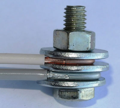
Disadvantage of copper wires - high cost. In Soviet homes, aluminum electrical wiring was used when building. Therefore, if partial replacement takes place, it is advisable to put aluminum wires. The only exceptions are those cases where instead of all the old wiring (up to the switchboard) a new one is installed. Then it makes sense to use copper. It is not permissible for copper and aluminum to come into direct contact, as this leads to oxidation. Therefore, a third metal is used to connect them.
You can make your own calculation of the cross section of the wire on the power for a three-phase circuit. To do this, you must use the formula: I=P/(U*1.73)where P - power, W; U - voltage, V; I - current, A. Then from the reference table select the cross-section of the cable depending on the calculated current. If the required value is not there, then the closest one that exceeds the calculated one is selected.
How to calculate by current
The amount of current flowing through a conductor depends on the length, width, resistivity of the latter and on temperature. When heated, the electric current decreases. Reference information is given for room temperature (18°С). To select the cable cross section according to the current use the table PUE (PUE-7 p.1.3.10-1.3.11 PERMANENT currents for wires, cords and cables with rubber or plastic insulation).
Table 3. Electrical current for copper wires and cords with rubber and PVC insulation
| Conductor cross-sectional area, mm² | Current, A, for wires laid | |||||
| openly | in one tube | |||||
| two solid conductors | three solid conductors | four single-core | one two-core | one three-core | ||
| 0,5 | 11 | - | - | - | - | - |
| 0,75 | 15 | - | - | - | - | - |
| 1 | 17 | 16 | 15 | 14 | 15 | 14 |
| 1,2 | 20 | 18 | 16 | 15 | 16 | 14,5 |
| 1,5 | 23 | 19 | 17 | 16 | 18 | 15 |
| 2 | 26 | 24 | 22 | 20 | 23 | 19 |
| 2,5 | 30 | 27 | 25 | 25 | 25 | 21 |
| 3 | 34 | 32 | 28 | 26 | 28 | 24 |
| 4 | 41 | 38 | 35 | 30 | 32 | 27 |
| 5 | 46 | 42 | 39 | 34 | 37 | 31 |
| 6 | 50 | 46 | 42 | 40 | 40 | 34 |
| 8 | 62 | 54 | 51 | 46 | 48 | 43 |
| 10 | 80 | 70 | 60 | 50 | 55 | 50 |
| 16 | 100 | 85 | 80 | 75 | 80 | 70 |
| 25 | 140 | 115 | 100 | 90 | 100 | 85 |
| 35 | 170 | 135 | 125 | 115 | 125 | 100 |
| 50 | 215 | 185 | 170 | 150 | 160 | 135 |
| 70 | 270 | 225 | 210 | 185 | 195 | 175 |
| 95 | 330 | 275 | 255 | 225 | 245 | 215 |
| 120 | 385 | 315 | 290 | 260 | 295 | 250 |
| 150 | 440 | 360 | 330 | - | - | - |
| 185 | 510 | - | - | - | - | - |
| 240 | 605 | - | - | - | - | - |
| 300 | 695 | - | - | - | - | - |
| 400 | 830 | - | - | - | - | - |
To calculate aluminum wires, use the table.
Table 4. Electrical current for aluminum wires and cords with rubber and PVC insulation
| Conductor cross-sectional area, mm² | Current, A, for wires laid openly | |||||
| openly | in one tube | |||||
| two solid conductors | three solid conductors | four single-core | one two-core | one three-core | ||
| 2 | 21 | 19 | 18 | 15 | 17 | 14 |
| 2,5 | 24 | 20 | 19 | 19 | 19 | 16 |
| 3 | 27 | 24 | 22 | 21 | 22 | 18 |
| 4 | 32 | 28 | 28 | 23 | 25 | 21 |
| 5 | 36 | 32 | 30 | 27 | 28 | 24 |
| 6 | 39 | 36 | 32 | 30 | 31 | 26 |
| 8 | 46 | 43 | 40 | 37 | 38 | 32 |
| 10 | 60 | 50 | 47 | 39 | 42 | 38 |
| 16 | 75 | 60 | 60 | 55 | 60 | 55 |
| 25 | 105 | 85 | 80 | 70 | 75 | 65 |
| 35 | 130 | 100 | 95 | 85 | 95 | 75 |
| 50 | 165 | 140 | 130 | 120 | 125 | 105 |
| 70 | 210 | 175 | 165 | 140 | 150 | 135 |
| 95 | 255 | 215 | 200 | 175 | 190 | 165 |
| 120 | 295 | 245 | 220 | 200 | 230 | 190 |
| 150 | 340 | 275 | 255 | - | - | - |
| 185 | 390 | - | - | - | - | - |
| 240 | 465 | - | - | - | - | - |
| 300 | 535 | - | - | - | - | - |
| 400 | 645 | - | - | - | - | - |
In addition to the electrical current, you will need to choose the conductor material and voltage.
For the approximate calculation of the cable cross-section according to the current, it should be divided by 10. If the table does not show the resulting cross-section, then you must take the nearest larger value. This rule is only suitable for cases where the maximum allowable current for copper wires does not exceed 40 A. For a range of 40 to 80 A, divide the current by 8. If aluminum cables are installed, you must divide by 6. This is because the thickness of the aluminum conductor is greater than that of the copper conductor to provide the same loads.
Calculating cable cross section by power and length
The length of the cable affects the voltage loss. Thus, at the end of the conductor, the voltage may decrease and be insufficient to operate an electrical appliance. For domestic power grids, these losses can be neglected. It will be enough to take a cable 10-15 cm longer. This reserve will be used for switching and wiring. If the ends of the wire are connected to the switchboard, the spare length should be even longer, since the circuit breakers.
When laying cables over long distances, the following must be taken into account voltage drop. Each conductor is characterized by electrical resistance. This parameter is affected by:
- The length of the wire, the unit of measurement - m. When it increases, losses increase.
- Cross-sectional area, measured in mm². With its increase the voltage drop decreases.
- Specific material resistance (reference value). Indicates the resistance of a wire that measures 1 square millimeter per 1 meter.
The voltage drop is numerically equal to the product of resistance and current. It is acceptable that this value should not exceed 5%. If this is not the case, you must use a cable with a larger cross-section. Algorithm for calculating the cross-sectional area of the wire according to maximum power and length:
- Depending on the power P, the voltage U and the factor cosf we find the current according to the formula: I=P/(U*cof). For power grids used in the home, cosf = 1. In industry, cosf is calculated as the ratio of active power to total power. The latter consists of the active and reactive powers.
- Use the PUE tables to determine the current-carrying cross-section of the conductor.
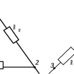
- Calculate the conductor resistance by the formula: Ro=ρ*l/Swhere ρ - resistivity of the material, l - length of the conductor, S - cross-sectional area. It is necessary to take into account the fact that the current goes through the cable not only in one direction, but also in reverse. Therefore, the total resistance: R = Ro*2.
- We find the voltage drop from the ratio: ΔU=I*R.
- Find the voltage drop in percent: ΔU/U. If the obtained value exceeds 5%, then select from the reference book the largest cross-section of the conductor.
Open and closed wiring
Depending on the location, wiring is divided into two types:
- closed;
- open.
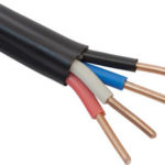
Today, hidden wiring is installed in apartments. In the walls and ceilings, special recesses are created, designed to accommodate the cable. After installing the conductors, the recesses are plastered. Copper wires are used as wires. Everything is planned in advance, since over time to increase the wiring or to replace the elements will have to dismantle the finish. Wires and cables that have a flat shape are more often used for concealed finishing.
For exposed wiring, the wires are installed along the surface of the room. Advantages are given to flexible conductors that have a round shape. They are easy to install in cable ducts and pass through the corrugation. When calculating the load on the cable, then take into account the method of laying the wiring.
Related articles: