Differential proportional-integral regulator is a device that is installed in automated systems to maintain a given parameter capable of change.
At first glance it is confusing, but you can explain PID regulation and for dummies, ie. people who are not quite familiar with electronic systems and devices.
Contents
What is a PID regulator?
A PID regulator is a device built into the control circuit with obligatory feedback. It is designed to maintain the set levels of the setpoints, for example, air temperature.
The device sends a control signal or output signal to a control device, based on the data received from sensors or sensors. The controllers have high transient accuracy and quality of execution of the set task.
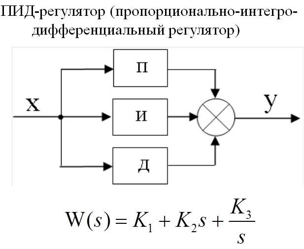
Three coefficients of PID controller and principle of operation
The operation of the PID controller is to provide an output signal of the power required to maintain the regulated parameter at a predetermined level. To calculate the index use a complex mathematical formula, which includes 3 coefficients - proportional, integral, differential.
Let's take as an object of regulation a tank with water in which it is necessary to maintain the temperature at a predetermined level by regulating the degree of opening of the valve with steam.
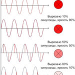
Proportional component appears at the moment of mismatch with input data. In simple words, it sounds like this - the difference between the actual temperature and the desired temperature is taken, multiplied by the adjustable coefficient and the output signal that should be applied to the valve is obtained. I.e. as soon as the degrees have fallen, the heating process is started, as soon as the temperature has risen above the desired level, it is switched off or even cooled down.
Next comes the integral component, which is designed to compensate for the effects of the environment or other disturbing influences on keeping our temperature at the set point. Since there are always additional factors affecting the devices being controlled, the number is already changing when the data arrives to calculate the proportional component. And the greater the external influences, the greater the fluctuations in the figure. There are spikes in the power supplied.
The integral component tries to return the temperature value based on past values, if it has changed. The process is described in more detail in the video below.
Then, the output of the regulator, according to the coefficient, is fed to raise or lower the temperature. Over time, a value is selected that compensates for external factors, and the jumps disappear.
The integral is used to eliminate errors by calculating the static error. The main thing in this process is to choose the right coefficient, otherwise the error (mismatch) will affect the integral component as well.
The third PID component is a differential component. It is designed to compensate for the effect of delays that occur between the impact on the system and the feedback. The proportional regulator delivers power until the temperature reaches the desired point, but there are always errors as the information travels to the instrument, especially with large values. This can lead to overheating. The differential predicts deviations caused by delays or environmental influences and reduces the power supplied in advance.
Setting up a PID controller
Setting up a PID controller is done using 2 methods:
- Synthesis involves calculating parameters based on the system model. Such tuning is accurate, but requires a deep knowledge of automatic control theory. It can only be done by engineers and scientists. Because it is necessary to take flow characteristics and make a lot of calculations.
- The manual method is based on the trial and error method. For this purpose, the data of an already ready system is taken as the basis, and some adjustments are made to one or more regulator coefficients. After switching on and observing the final result, the parameters are changed in the right direction. And so on until the desired level of operability is achieved.
The theoretical method of analysis and tuning is rarely used in practice, which is due to ignorance of the characteristics of the control object and a lot of possible disturbing influences. Experimental methods based on observation of the system are more common.
Modern automated processes are implemented as specialized modules under the control of programs to adjust regulator coefficients.
Purpose of PID regulator
The PID regulator is designed to maintain some value, such as temperature, pressure, tank level, flow in a pipeline, concentration of something, etc., at a required level by changing the control action on actuators, such as automatic control valves, using proportional, integrating, differentiating values for its setting.
The purpose of the use is to obtain a precise control signal that is capable of controlling large industries and even power plant reactors.
Example of a temperature control circuit
PID controllers are often used in temperature control, let's use a simple example of heating water in a tank to look at this automatic process.
The tank is filled with liquid that needs to be heated to the desired temperature and maintained at the desired level. Inside the tank there is a sensor for measuring temperature - thermocouple or resistance thermometer and is directly connected to the PID controller.
We will supply steam to heat the liquid, as shown in the figure below, with the automatic control valve. The valve itself receives a signal from the controller. The operator enters the temperature set point value in the PID controller that needs to be maintained in the tank.
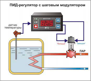
If the regulator coefficients are incorrect, the water temperature will jump and the valve will be fully open or fully closed. In this case the PID coefficients must be calculated and entered again. If everything is done correctly, after a short period of time the system will equalize the process and the temperature in the tank will be maintained at the set point, with the degree of opening of the control valve will be in the middle position.
Related articles: