Thermocouple is a device for measuring temperatures in all branches of science and technology. This article provides a general overview of thermocouples with a breakdown of the design and principle of operation of the device. Varieties of thermocouples with their brief characteristics are described, and an evaluation of the thermocouple as a measuring device is given.
Contents
Thermocouple Design
The principle of operation of a thermocouple. Seebeck effect
The thermocouple is based on the thermoelectric effect discovered by the German physicist Tomas Seebeck in 1821.
The phenomenon is based on the emergence of electricity in a closed electrical circuit when exposed to a certain ambient temperature. Electric current is generated when there is a temperature difference between two conductors (thermoelectrodes) of different composition (dissimilar metals or alloys) and is maintained by keeping their contacts (junctions) in place. The device displays the measured temperature value on the screen of the connected secondary device.
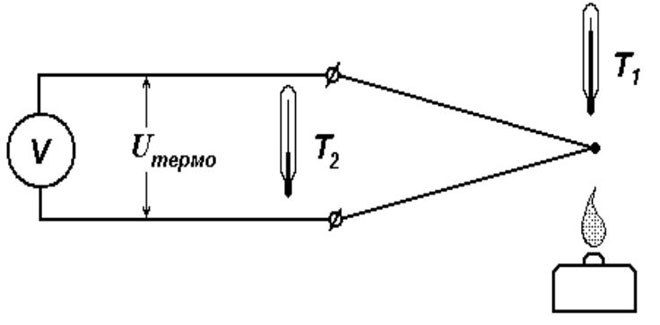
The output voltage and temperature are in a linear relationship. This means that an increase in the measured temperature results in a higher millivolt value at the free ends of the thermocouple.
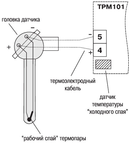
The junction at the temperature measurement point is called the "hot junction" and the point where the wires are connected to the transmitter is called the "cold junction".
Cold Junction Temperature Compensation (CJC)
Cold junction compensation (CJC) is a correction made in the form of a correction to the final reading when measuring the temperature at the connection point of the thermocouple's free ends. This is due to discrepancies between the actual cold junction temperature and the calculated readings from the calibration chart for the cold junction temperature at 0°C.
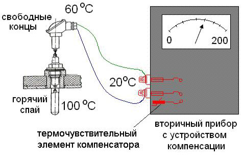
The CHS is a differential method in which the absolute temperature reading is derived from the known value of the cold junction temperature (another name for the reference junction).
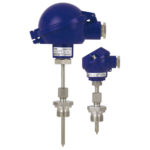
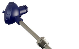
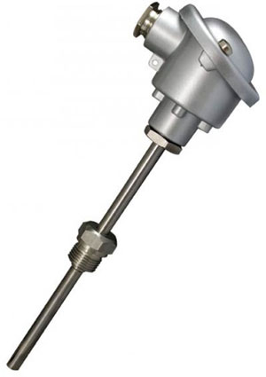
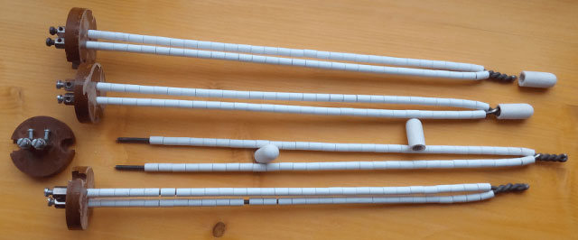
Thermocouple Design
The design of a thermocouple takes into account the influence of such factors as the "aggressiveness" of the external environment, the aggregate state of the substance, the range of temperatures to be measured, and others.
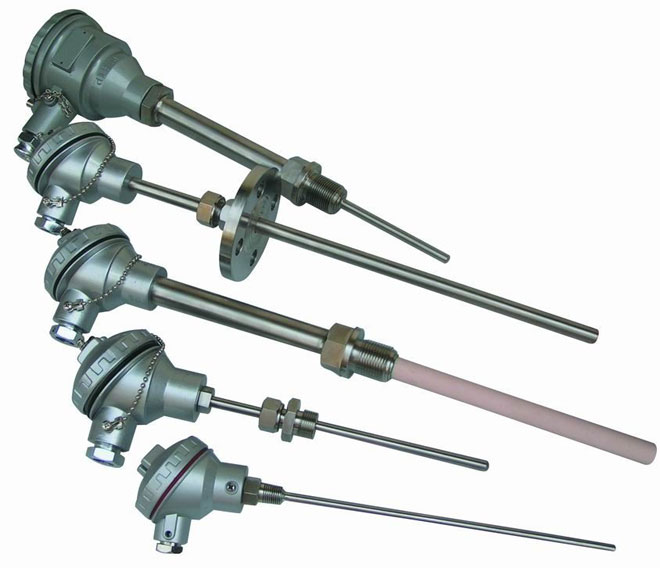
Features of thermocouple design:
1) Conductor pairs are connected to each other by twisting or stranding with further arc welding (rarely soldering).
IMPORTANT: The twisting method is not recommended because of the rapid loss of junction properties.
2) The thermocouple electrodes must be electrically insulated along their entire length, except for the touch point.
3) The method of isolation is chosen taking into account the upper temperature limit.
- Up to 100-120°C - any insulation;
- Up to 1300°C - porcelain tubes or beads;
- Up to 1950°C - Al2O3;
- Above 2000°С - tubes from MgO, BeO, ThO2ThO , ZrO2.
4) Protective cover.
Material must be thermally and chemically resistant, with good thermal conductivity (metal, ceramics). Using a sheath prevents corrosion in certain media.
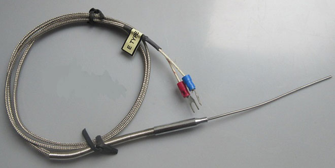
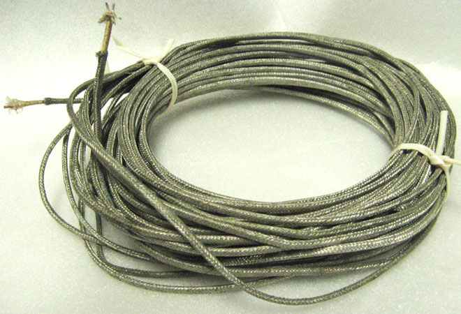
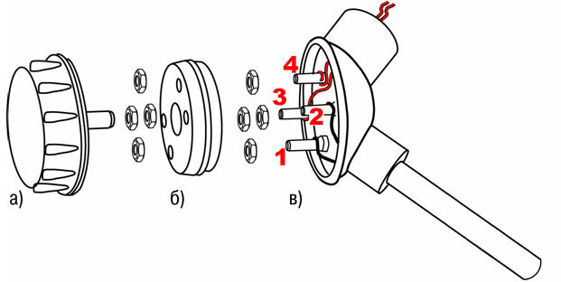
Extension (expansion) wires
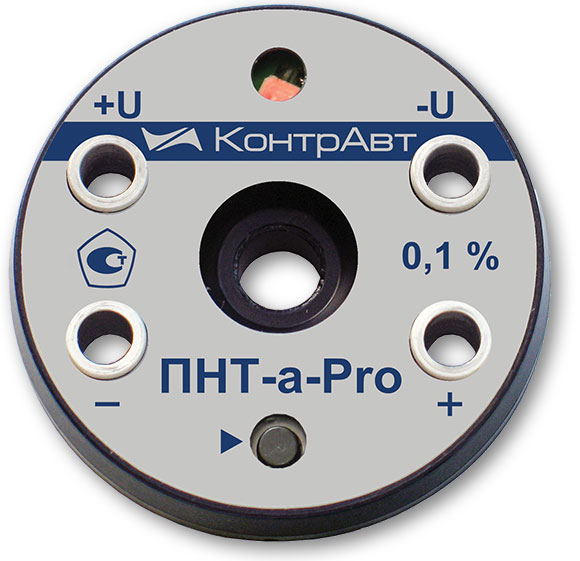
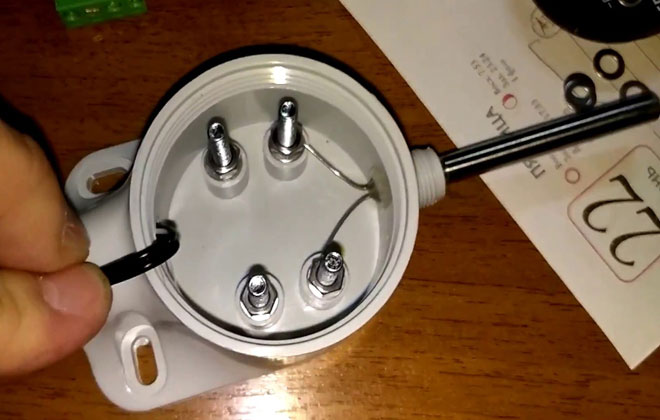
This type of wire is needed to extend the ends of the thermocouple to a secondary device or barrier. The wires are not used if the thermocouple has a built-in transmitter with a unified output signal. The most widespread application is the normalizing transducer placed in a standard sensor terminal head with a unified 4-20mA signal, the so-called "tablet".
The material of wires can coincide with the material of thermoelectrodes, but most often it is replaced with a cheaper one, taking into account the conditions preventing formation of parasitic (induced) thermo-electrodes. The use of extending wires also helps to optimize production.
Tips and tricks! To correctly determine the polarity of the compensation wires and their connection to the thermocouple, remember the MM mnemonic rule - minus is magnetic. That is, take any magnet and the minus of the compensation will be magnetic, unlike the plus.
Types and kinds of thermocouples
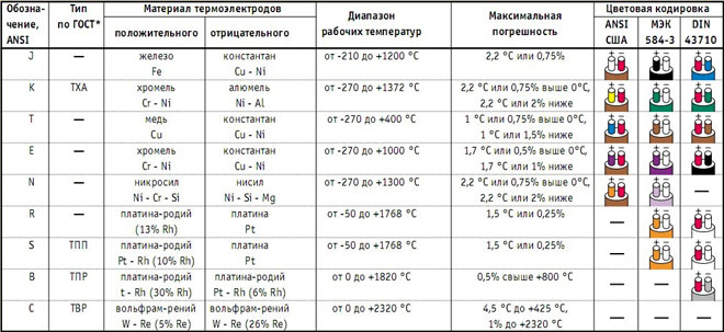
The variety of thermocouples is due to the different combinations of metal alloys used. Thermocouple selection is based on the industry and the required temperature range.
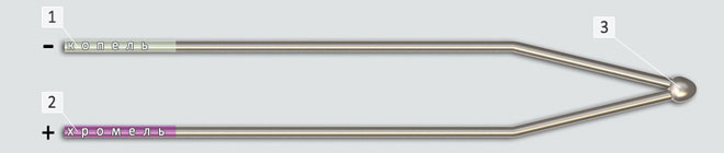
Chromel-alumel thermocouple (TXA)
Positive electrode: chromel alloy (90% Ni, 10% Cr).
Negative electrode: alumel alloy (95% Ni, 2% Mn, 2% Al, 1% Si).
Insulating material: porcelain, quartz, metal oxides, etc.
Temperature range from -200 ° C to 1300 ° C short-term and 1100 ° C long-term heating.
Operating environment: inert, oxidizing (O2=2-3% or totally excluded), dry hydrogen, short-term vacuum. In a reducing or redox atmosphere in the presence of a protective sheath.
Disadvantages: easy to deform, reversible instability of thermal EMF.
Possible cases of corrosion and embrittlement of alumel in the presence of traces of sulfur in the atmosphere and chromel in a weakly oxidizing atmosphere ("green clay").
Chromel-copper thermocouple (TCC)
Positive electrode: chromel alloy (90% Ni, 10% Cr).
Negative electrode: copel alloy (54.5% Cu, 43% Ni, 2% Fe, 0.5% Mn).
Temperature range from -253°C to 800°C long-term and 1100°C short-term heating.
Operating environment: inert and oxidizing, short-term vacuum.
Disadvantages: deformation of the thermocouple.
Perhaps evaporation of chromium in a long vacuum; reaction with an atmosphere containing sulfur, chromium, fluorine.
Iron-constantan thermocouple (PCT).
Positive electrode: technically pure iron (mild steel).
Negative electrode: constantan alloy (59% Cu, 39-41% Ni, 1-2% Mn).
Used for measurements in reducing, inert media and vacuum. Temperatures from -203 ° C to 750 ° C long and 1100 ° C short-term heating.
The application is folded on the joint measurement of positive and negative temperatures. It is not advantageous to use only for negative temperatures.
Disadvantages: deformation of the thermocouple, low corrosion resistance.
Change of physical and chemical properties of iron around 700 °С and 900 °С. Interacts with sulfur and water vapor with the formation of corrosion.
Tungsten-rhenium thermocouple (TVR)
Positive electrode: alloys BP5 (95% W, 5% Rh)/BP5 (BP5 with silica and aluminum additive)/BP10 (90% W, 10% Rh).
Negative electrode: alloys BP20 (80% W, 20% Rh).
Insulation: ceramic of chemically pure metal oxides.
Features include mechanical strength, temperature resistance, low sensitivity to contamination, and ease of fabrication.
Measuring temperatures from 1800 ° C to 3000 ° C, the lower limit - 1300 ° C. Measurements are taken in an inert gas, dry hydrogen or vacuum environment. In oxidizing media only for measurements in fast flowing processes.
Disadvantages: poor reproducibility of thermal EMF, its instability during irradiation, unstable sensitivity in the temperature range.
Tungsten-molybdenum (TM) thermocouple
Positive electrode: tungsten (technically pure).
Negative electrode: molybdenum (technically pure).
Insulation: alumina ceramic, protection with quartz tips.
Inert, hydrogen or vacuum environment. Short-term measurements in oxidizing environments possible in the presence of insulation. The range of measured temperatures is 1400-1800 ° C, the limit operating temperature is about 2400 ° C.
Disadvantages: poor reproducibility and sensitivity of thermo-EDC, polarity inversion, embrittlement at high temperatures.
Thermocouples platinum-rhodium-platinum (TPP)
Positive electrode: platinum-rhodium (Pt with 10% or 13% Rh).
Negative electrode: platinum.
Insulation: quartz, porcelain (regular and refractory). Up to 1400 °С - ceramics with high content of Al2O3O, above 1400 °С - chemically pure Al2O3.
Maximum operating temperature 1400 ° C for a long time, 1600 ° C for a short time. Measurement at low temperatures is not normally performed.
Operating environment: oxidizing and inert, reducing environment in the presence of protection.
Disadvantages: high cost, instability under irradiation, high sensitivity to contamination (especially platinum electrode), metal grain growth at high temperatures.
Platinum-Rhodium-Platinum-Rhodium Thermocouples (PRT)
Positive electrode: Pt alloy with 30% Rh.
Negative electrode: Pt alloy with 6% Rh.
Medium: oxidizing, neutral and vacuum. Use in reducing and metal or non-metal vapor-containing environments in the presence of protection.
Maximum working temperature: 1600°C long term, 1800°C short term.
Insulation: Ceramics made of Al2O3 high purity.
Less susceptible to chemical contamination and grain growth than platinum-rhodium thermocouple.
Thermocouple connection diagram
- Connection of the potentiometer or galvanometer directly to the conductors.
- Connection with compensation wires;
- Connection by conventional copper wires to a thermocouple having a unified output.
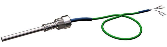
Thermocouple Conductor Color Standards
Color-coded conductor insulation helps distinguish thermocouple electrodes from each other for proper connection to terminals. Standards vary by country; there are no specific color designations for conductors.
IMPORTANT: It is necessary to find out the standard used at the factory to prevent errors.
Accuracy of measurement
Accuracy depends on the type of thermocouple, temperature range measured, material purity, electrical noise, corrosion, junction properties, and manufacturing process.
Thermocouples are assigned a tolerance class (standard or special) that establishes the confidence interval of the measurement.
IMPORTANT: Characteristics at the time of manufacture change during operation.
Measurement speed
The responsiveness is determined by the ability of the primary transducer to respond quickly to temperature jumps and the subsequent flow of input signals from the measuring instrument.
Factors that increase responsiveness:
- Proper installation and calculation of the length of the primary transducer;
- When using a transmitter with a protective thermowell, reduce the mass of the assembly by selecting a smaller diameter of the thermowell;
- Minimize the air gap between the primary transducer and the thermowell;
- Using a spring loaded primary transducer and filling the cavities in the thermowell with thermally conductive filler;
- Fast moving media or media with higher density (liquid).
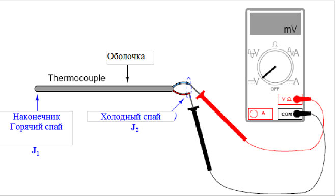
Checking thermocouple performance
To verify operation, connect a special measuring device (tester, galvanometer or potentiometer) or measure the output voltage with a millivoltmeter. If the arrow or digital indicator fluctuates, the thermocouple is good, otherwise the device must be replaced.
Causes of thermocouple failure:
- Failure to use a protective shielding device;
- Changing the chemical composition of the electrodes;
- Oxidative processes occurring at high temperatures;
- Breakage of measuring instrument, etc.
Advantages and disadvantages of using thermocouples
The advantages of using this device can be called:
- Large temperature range of measurements;
- High accuracy;
- Simplicity and reliability.
The disadvantages should include:
- Implementation of continuous control of the cold junction, verification and calibration of the control equipment;
- Structural changes of metals during manufacturing of the device;
- Dependence on atmospheric composition, sealing costs;
- Measurement error due to exposure to electromagnetic waves.