The system of three-phase electric current was developed in the late XIX century by Russian scientist M.O.Dolivo-Dobrovolsky. Three phases with voltages shifted by 120 degrees in relation to each other, among other advantages, allow to easily create a rotating magnetic field. This field entrains the rotors of the most common and simplest three-phase asynchronous electric motors.
The three stator windings of such electric motors are in most cases connected by a star or delta circuit. The terms "star" and "delta", abbreviated S and D, are used in foreign literature. A more common mnemonic designation is D and Y, which can sometimes lead to confusion - the letter D can be labeled both "star" and "triangle".
Contents
Phase and line voltages
To understand the differences between winding connections, we first need to understand the concepts of phase voltages and line voltages. Phase voltage is the voltage between the beginning and the end of one phase. Linear - between the same terminals of different phases.
For a three-phase network, line voltages are voltages between phases, for example A and B, and phase voltages are voltages between each phase and the neutral conductor.
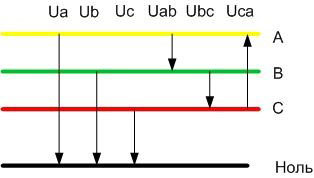
So the voltages Ua, Ub, Uc will be phase voltages and Uab, Ubc, Uca will be line voltages. These voltages differ by a factor of two. Thus, for a 0.4 kV household and industrial network, the line voltages are 380 volts, and the phase volt voltages are 220 volts.
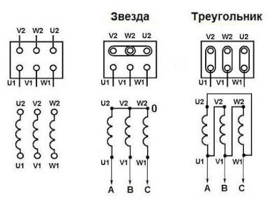
Connection of the motor windings in a star connection
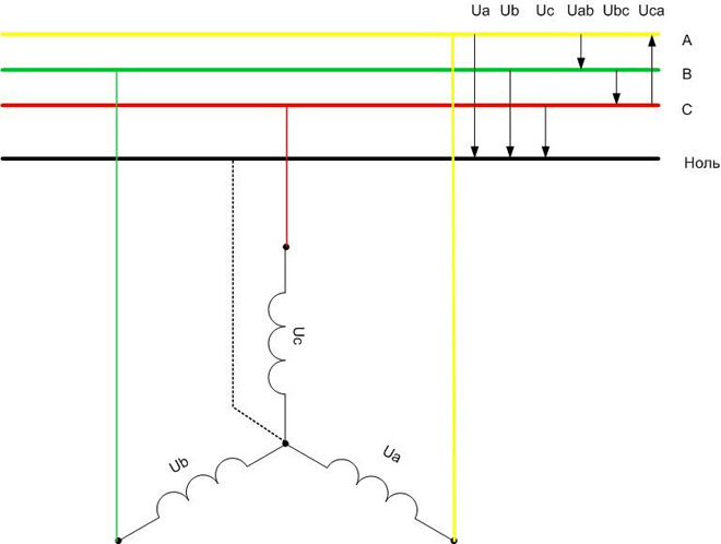
In a star connection, the three windings are connected at a common point with their star points. The free ends are each connected to their own phase. In some cases the common point is connected to the neutral busbar of the power system.
From the figure you can see that for this connection, each winding has a network phase voltage applied to it (for 0.4 kV networks - 220 volts).
Connection of electric motor windings according to delta circuit
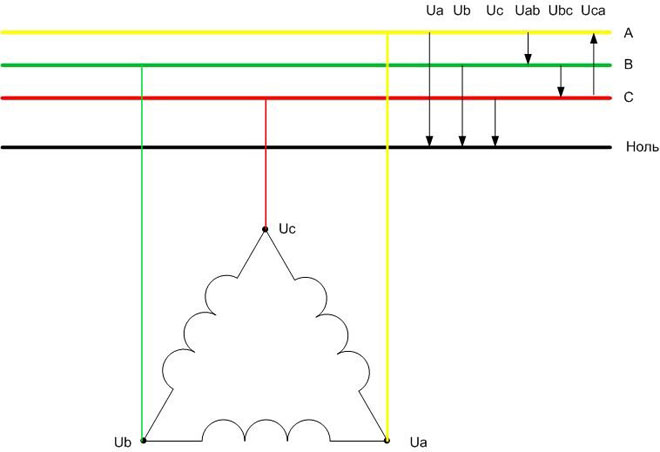
In the delta circuit, the ends of the windings are connected in series. A peculiar circle is obtained, but the name "delta" is accepted in literature because of the frequently used layout. The neutral wire in this variant has nowhere to connect.
Obviously, the voltages applied to each winding will be linear (380 volts per winding).
Comparison of the wiring diagrams with each other
To compare the two circuits against each other, we have to calculate the electrical power developed by the electric motor with one or the other connection. To do this, consider the concepts of line current (Ilin) and phase current (Iphase). The phase current is the current flowing through the phase winding. Linear current flows through a conductor connected to the output of the winding.
In networks up to 1000 volts, the source of electricity is a transformerThe secondary winding of a transformer with a star connection (otherwise the neutral conductor cannot be arranged) or a generator whose windings are connected in the same way.
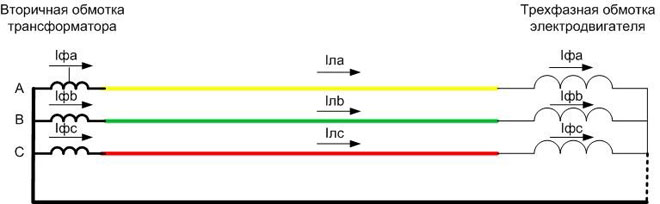
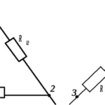
It can be seen from the figure that with star connection the currents in the conductors and the currents in the motor windings are equal. The current in the phase is determined by the phase voltage:
![\[I_faz=\frac{U_faz}{Z}\]](https://electros.tomathouse.com/wp-content/ql-cache/quicklatex.com-f4518d61a0fe68758ecd5221efdc8d3a_l3.png "Rendered by QuickLaTeX.com")
where Z is the winding resistance of one phase, they can be taken equal. It may be written that
![\I_faz=I_lin\]](https://electros.tomathouse.com/wp-content/ql-cache/quicklatex.com-be70a1b78bb7c7fd8a17275f34f188ee_l3.png "Rendered by QuickLaTeX.com")
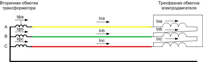
For delta connection currents are different - they are determined by line voltages applied to resistance Z:
![\[I_faz=\frac{U_lin}{Z}\]](https://electros.tomathouse.com/wp-content/ql-cache/quicklatex.com-04741f4af117efbb0661c26c4ee10334_l3.png "Rendered by QuickLaTeX.com")
Hence, for this case  .
.
Now we can compare the total power ( ) consumed by motors with different circuits.
- for a star connection the total power is
 ;
; - for delta connection the total power is
 .
.
Thus, when a star connection is made, the motor develops three times less power than when a delta connection is made. This also has other positive effects:
- inrush currents are reduced;
- the motor runs and starts more smoothly;
- the electric motor can handle short-time overloads well;
- thermal mode of asynchronous motor becomes more sparing.
The other side of the coin - a motor with "star" winding cannot develop the maximum power. In some cases, the torque may not even be enough to spin the rotor.
Ways of switching star-delta circuits
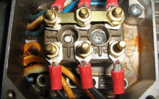
Most motors are designed in such a way that they can be switched from one connection diagram to the other. To do this, the starts and ends of the windings are brought out on the terminal so that by simply changing the position of the pads it is possible to change from star to delta and vice versa.
The owner of the electric motor can choose what he needs - a soft start with low starting currents and smooth operation or the highest power developed by the motor. If both are required, it is possible to switch automatically with powerful contactors.
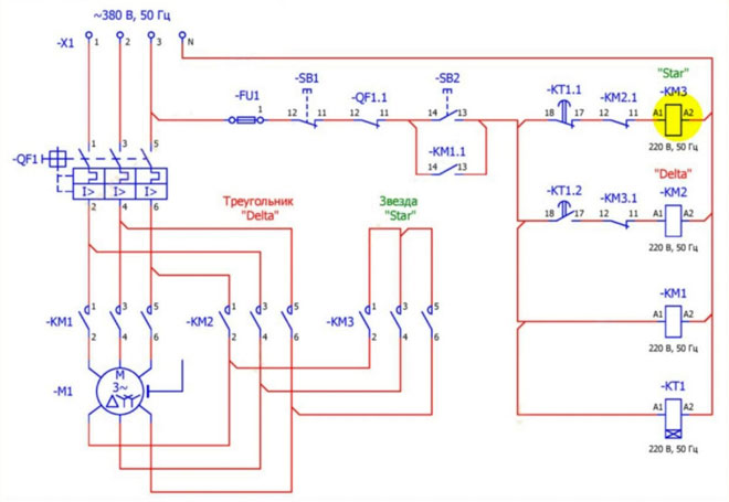
When the SB2 starting button is pressed, the motor is switched on in a star configuration. Contactor KM3 is energized, its contacts short-circuit the motor winding leads on one side. The opposite leads are connected to the mains, each to its own phase via the contacts of KM1. When this contactor is energized, three-phase voltage is applied to the windings and the electric motor rotor is driven. After a certain time set on the relay KT1, the coil KM3 is switched, it is de-energized, the contactor KM2 is switched on, switching the windings into a delta.
The change-over takes place after the engine has gained revolutions. This moment can be monitored by the speed sensor, but in practice it is simpler. The change-over is controlled time relay - after 5-7 seconds it is considered that the starting process is completed and the engine can be switched to the maximum power. It is not necessary to delay this moment, because long work with exceeding the permissible load for "star" may lead to failure of the electric drive.
The following must be kept in mind when implementing this mode:
- Starting torque of the motor with windings connected "star" is much lower than the value of this characteristic of electric motor with connection "delta", therefore, starting of electric motor with heavy starting conditions in this way is not always possible. It simply will not come into rotation. Such cases include electric drive pumps operating with back-pressure, etc. Such problems are solved by means of phase-rotor motors by smoothly increasing the excitation current at start-up. Successful star-starting is used with centrifugal pumps operating on a closed gate, in case of fan loads on the motor shaft, etc.
- Electric motor windings must be able to withstand the line voltage of the mains. It is important not to confuse D/Y 220/380 volt motors (typically low-power induction motors up to 4 kW) and D/Y 380/660 volt motors (typically 4 kW and above). The 660 volt grid is almost never used, but only electric motors with this voltage rating can be used for star-delta switching. The 220/380 drive can only be used in a three-phase system with a star connection. They must not be used in the switching circuit.
- There must be a pause between switching off the star contactor and switching on the delta contactor to avoid overlapping. But it must not be increased beyond its limit to prevent the motor from stopping. If you make the circuit yourself, it may be necessary to pick it up experimentally.
Reverse switching is also used. It makes sense if a powerful motor temporarily works with a small load. In this case, its power factor is low, because the active power consumption is determined by the load level of the electric motor. The reactive power is mainly determined by the inductance of the windings, which is independent of the load on the shaft. In order to improve the ratio of active and reactive power consumption, the windings can be switched to a star circuit. This can also be done manually or automatically.
The switching scheme can be assembled on discrete elements - time relays, contactors (starters), etc. Ready-made solutions are also available that combine the automatic switching circuit in one housing. It is only necessary to connect the electric motor to the output terminals and the power supply from the three-phase network. Such devices may have different names, such as "starting time relay", etc.
The connection of motor windings according to different schemes has its own advantages and disadvantages. The basis of competent operation is to know all the pros and cons. Then the motor will last a long time, bringing the maximum effect.
Related articles: