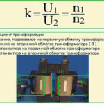
Electrical apparatus with two, three or more windings, installed statically in a power grid. A power transformer changes alternating voltage and current without frequency deviation. The converter used in the secondary power supply is called a step-down device. Booster structures increase voltage and are used in high-voltage transmission lines with high power, capacity and capacity.
Contents
Applications
Power transformers are part of systems designed to generate electricity. Power plants use energy of atom, organic, solid or liquid fuel, operate on gas or use the power of water flow, but converters of output indicators of substations are necessary for normal functioning of consumer and production lines.
The units are installed in the networks of industrial facilities, rural enterprises, defense complexes, oil and gas developments. The direct purpose of a power transformer - to lower and raise the voltage and current - is used to operate transportation, housing, commercial infrastructure, and network distribution facilities.
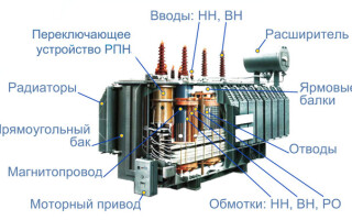
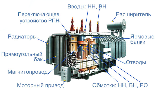
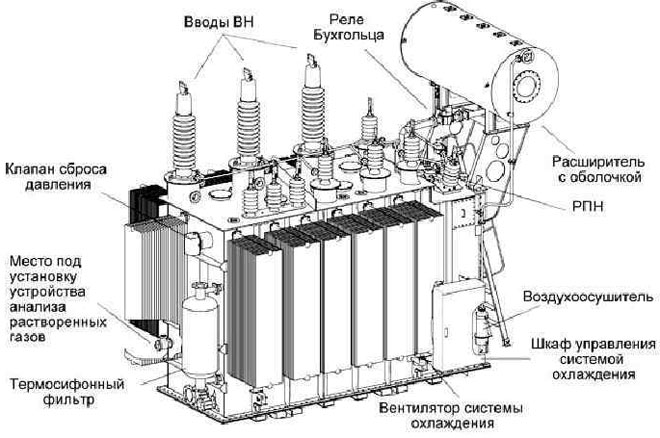
Main parts and systems
The supply voltage and load are supplied to the inlets, which are located on an inner or outer terminal block. The contact is fastened by bolts or special connectors. In oil-filled units, the bushings are arranged externally on the sides of the tank or on the cover of the removable housing.
Transmission from the internal windings goes on flexible dampers or threaded rods made of non-ferrous metals. Power transformers and their housings are insulated from the studs with a porcelain or plastic layer. Gaps are eliminated by gaskets made of material resistant to oil and synthetic liquids.
Coolers reduce the temperature of the oil from the top region of the tank and transfer it to the side bottom layer. The cooling device of a power oil transformer is represented by:
- An external circuit that removes heat from the medium;
- An internal circuit that heats the oil.
Coolers are of different types:
- radiators - a set of flat channels with welding on the end, located in the plates to communicate between the lower and upper manifolds;
- corrugated tanks - installed in low and medium-power units, they are both the tank for temperature reduction and the working tank with the folded surface of the walls and the bottom box
- fans - they are used in large transformer units for forced cooling of the flow;
- heat exchangers - they are used in large units to move synthetic fluids with a pump, since the organization of natural circulation requires a lot of space;
- water-oil units - tubular heat exchangers by classical technology;
- circulating pumps - hermetically sealed designs with full immersion of the motor in the absence of gland gaskets.
Voltage transformation equipment is provided with regulating devices to change the number of working turns. The voltages on the secondary winding are modified by means of a switch for the number of coils or set by bolt connection with the choice of jumper arrangement. This is how the leads of a grounded or de-energized transformer are connected. Regulating modules convert voltages in small ranges.
Depending on the conditions, helix number switches are divided into types:
- devices that operate when the load is off;
- elements that function when the secondary winding is closed to resistance.
Attachment equipment.
The gas relay is located in the connection tube between the expansion and operating tanks. The device prevents decomposition of insulating organics, oil when overheated and minor damage to the system. The device responds to gassing in case of malfunctions, gives an alarm or shuts down the system completely in case of a short circuit or dangerously low liquid level.
Thermocouples are placed on top of the tank in pockets to measure temperature. They work on the principle of mathematical calculation to identify the warmest part of the unit. Modern sensors are based on fiber optic technology.
The continuous regeneration unit is used for oil recovery and purification. As a result of operation, slag is formed in the mass and air enters it. Regeneration units come in two types:
- Thermosiphon modules, which use the natural movement of heated layers upward and passing through the filter, then lowering the cooled flows to the bottom of the tank;
- quality adsorption units forcibly pump the oil through the filters with a pump, are located separately on the foundation, are used in schemes of large-sized converters.
Oil protection modules are an open-type expansion tank. The air above the surface of the mass is passed through moisture absorbers with silica gel. The adsorbent substance turns pink at maximum humidity, which serves as a signal to replace it.
An oil seal is installed on top of the expander. This is a device for reducing air humidity, operating on transformer dry oil. The module is connected to the expansion tank by means of a socket. A vessel with internal separation in the form of several walls in the shape of a labyrinth is welded on top. The air passes through the oil, gives off moisture, then is cleaned with silica gel and flows into the expander.
Control devices
The pressure relief device prevents an emergency head surge due to a short circuit or severe oil decomposition and is provided in the design of heavy-duty units in accordance with GOST 11677-1975. The device is made in the form of a discharge pipe, located at an angle to the transformer cover. At the end there is a sealed diaphragm, capable of instantly unfolding and letting the exhaust.
In addition, there are other modules installed in the transformer:
- Oil level sensors in the tank, equipped with a dial or made in the form of a glass tube of communicating vessels, are placed at the end of the expander.
- Built-in transformers are installed inside the unit or close to the earthing sleeve on the side of bushings of through-type or low-voltage busbars. In this case there is no need for a large number of separate converters in the substation with internal and external insulation.
- The combustible impurities and gas detector detects hydrogen in the oil mass and squeezes it through the diaphragm. The instrument shows the initial degree of gassing before the concentrated mixture makes the monitoring relay act.
- The flowmeter monitors the oil loss in substations operating on the principle of forced temperature reduction. The device measures the head difference and determines the pressure on both sides of the resulting obstruction in the flow. In water-cooled units, the flow meters read the moisture consumption. The elements are equipped with an alarm in case of an accident and a dial to determine the values.
Operating principle and modes of operation
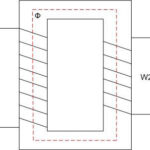
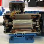
The simple transformer is equipped with a core of permalloy, ferrite and two windings. The magnetic circuit includes a set of ribbon, plate or molded elements. It moves the magnetic flux generated by electricity. The principle of a power transformer is to convert current and voltage values by induction, while the frequency and shape of the charged particles remains constant.
In step-up transformers, the circuit involves a higher voltage on the secondary winding than on the primary coil. In step-down units, the input voltage is higher than the output voltage. A core with spiral coils is placed in a tank of oil.
When the alternating current is switched on, an alternating magnetic field is generated on the primary coil. It closes on the core and affects the secondary circuit. An electromotive force is generated, which is transmitted to the connected loads at the transformer output. There are three modes of operation of the station:
- Idle is characterized by the open state of the secondary coil and no current inside the windings. Idle electricity flows in the primary coil, which is 2-5% of the rating.
- Operation under load takes place with power and consumers connected. Power transformers show energy in two windings, operation in this regulation is common for the unit.
- Short-circuit, in which the resistance on the secondary coil remains the only load. The mode reveals losses to warm up the core windings.
Idle Mode
Electricity in the primary coil is equal to the value of the alternating magnetizing current, the secondary current shows zero values. The electromotive force of the primary coil in the case of a ferromagnetic tip completely replaces the source voltage, there are no load currents. No-load operation reveals instantaneous turn-on losses and eddy currents, determines reactive power compensation to maintain the required output voltages.
In a unit without a ferromagnetic conductor, there are no magnetic field change losses. The no-load current is proportional to the primary winding resistance. The ability to resist the passage of charged electrons is transformed by changes in current frequency and induction size.
Short-circuit operation
A small alternating voltage is applied to the primary coil, and the outputs of the secondary coil are short-circuited. The input voltages are adjusted so that the short-circuit current corresponds to the calculated or rated value of the unit. The size of the short-circuit voltage determines the losses in the transformer coils and the flow to counteract the conductor material. Part of the DC current overcomes resistance and is converted to thermal energy, the core is warmed.
The short-circuit voltage is calculated as a percentage of the nominal value. The parameter obtained during operation in this mode is an important characteristic of the unit. By multiplying it by the short-circuit current, the power loss is obtained.
Operating mode
When a load is connected, particle motion occurs in the secondary circuit, causing magnetic flux in the conductor. It is directed in the other direction from the flux produced by the primary coil. In the primary coil, there is a mismatch between the electromotive force of the induction and the power supply. The current in the primary coil rises until the magnetic field gains its original value.
The magnetic flux of the induction vector characterizes the passage of the field through a selected surface and is determined by the time integral of the instantaneous force index in the primary coil. The index is shifted in phase at 90˚ in relation to the driving force. The induced EMF in the secondary coincides in shape and phase with that in the primary coil.
Types and kinds of transformers
Power units are used in the case of high-voltage current conversion and large capacities, they are not used to measure the performance of the network. Installation is justified in the case of the difference between the voltage in the network of the energy producer and the circuit going to the consumer. Depending on the number of phases, stations can be classified as single-coil or multiwinding units.
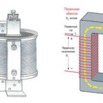
A single-phase power converter is statically installed, characterized by mutually inductively coupled windings that are stationary. The core is designed as a closed frame and differentiates between bottom yoke, top yoke and side rods where the coils are located. The active elements are the coils and the magnetic circuit.
The wraps on the rods are in the established combinations in the number and shape of coils or arranged in concentric order. Cylindrical wraps are the most common and often used. Structural elements of the unit fix the parts of the station, insulate the passages between the coils, cool the parts and prevent breakages. Longitudinal insulation covers individual coils or combinations of coils on the core. Main dielectrics are used to prevent the transition between ground and windings.
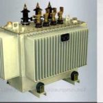
In three-phase electrical circuits, two-winding and three-winding units are placed to distribute the load evenly between inputs and outputs or single-phase substitution devices. Oil-cooled transformers contain a magnetic core with windings, which are located in a tank of substance.
The twins are arranged on a common conductor, with primary and secondary circuits that interact due to the occurrence of a common field, current or polarization as charged electrons move in a magnetic medium. This common induction makes it difficult to determine the performance of the plant, high and low voltage. A transformer substitution plan is used in which the windings interact in an electrical rather than magnetic environment.
The principle of equivalence of the action of the dissipation fluxes to the work of the resistances of the inductive coils that carry the current is applied. A distinction is made between coils with active induction resistance. The second type is magnetically coupled coils that transmit particles without scattering fluxes with minimal hindering properties.
Related articles: