To measure the value of resistance, as well as to identify defects in cables and wiring of electrical networks, use a specially designed for this device megohmmeter.
Three words are clearly recognizable in the name of the device:
"Mega", "Ohm", and "Meter", where the first word refers to the value of the measured quantity, the second to the unit of measurement, and the third derived from the word "to measure".
The working process of the megohmmeter is based on the principles of Ohm's law concerning the sections of the electric circuit, so any modification of the device contains in the inner part of the case:
- current measuring system (ammeter);
- a set of output terminals;
- a constant voltage generator.
Design features of voltage generators can vary within quite wide limits. They are based on simple manual dynamos, which were used in the past. Modern generators are equipped with built-in or external power sources.
The output power and voltage of a generator can vary within several intervals or have a single, fixed value.
The connecting wires are connected to the terminals of the megohmmeter on one side and are fixed in the circuit to be measured with "crocodiles" on the other side. These are special devices designed for a more secure connection.
With the help of an ammeter, which is built inside the unit, the values of the current passing through the circuit are measured.
Note! with the known and graduated voltage of the generator, the units of resistance are also calibrated, that is, the scale located on the measuring head shows megaohms, kilohms, or both together.
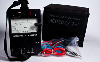
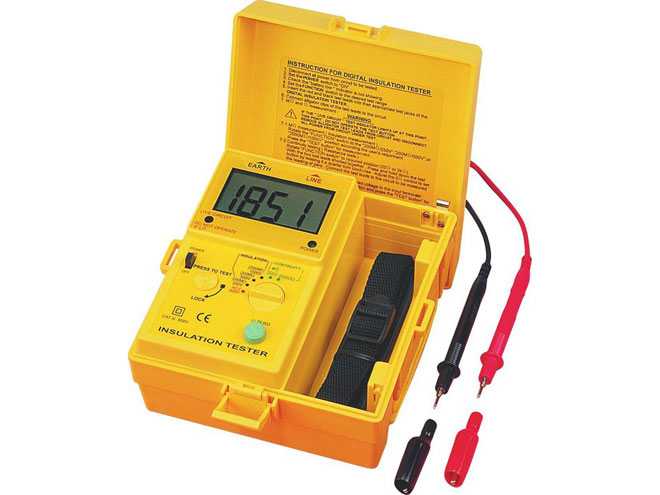
On the scale of one of the most reliable proven analog megohmmeters produced some fifty years ago, the M4100/5, there are two scales, allowing for a measurement on two boundaries. New technology displays the resistance readings more clearly. The digital display shows an already processed digital signal.
Contents
Arrow megohmmeter and its construction
A simplified electrical circuit, typical of analog devices is equipped with the following components:
- a direct current generator;
- The measuring head, which consists of two interacting frames (operating and counteracting);
- toggle switch between measurement limits, which allows you to adjust the operation of various resistor circuits, designed to correct the output voltage and operating modes of the head;
- Current limiting resistor.
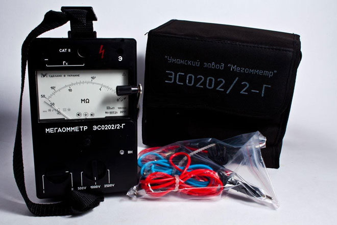
In turn, dielectric sealed rugged housing of this unit is equipped with:
- a handle for comfortable transportation;
- a folding portable generator handle, by turning which the voltage is produced;
- a lever, by means of which the measurement modes are switched;
- output terminals designed to make the entire circuit work (the terminals are connected to the connecting wires).
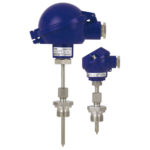
Most megohmmeter models have three output terminals for connection. Each terminal is named Ground (G), Line (L), and Shield (E).
H and L are for measuring insulation resistance. E - in order to eliminate the influence of current losses in the case of measuring in the area of two parallel cable cores.
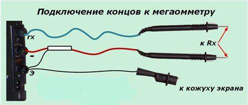
The device is equipped with a special measuring wire with a characteristic design and a shielded end equipped with two terminals. One of them is marked with the letter "E". What does it mean? It means that it should be connected to the appropriate terminal on the megohmmeter.
For megohmmeters, based on the operation of the external network, the same principle of operation is characteristic, the knob is no longer rotated, that is, in order to give out voltage for the tested circuit, you should simply hold down the specially designed for this purpose button. A device capable of outputting more than one combination of voltages is equipped accordingly with several buttons. There can be two, three... even several sets of combinations. Such megohmmeters have a more complex internal structure.
Pay attention! Devices have high voltages, so when using them, safety precautions should be observed.
Negligent attitude in the work with a high level of danger is unacceptable. So how to properly use a megohmmeter? From all of the above, the conclusion suggests itself:
According to the safety measures when working with a megohmmeter, only a specially trained and prepared person is allowed to take measurements. His specialization should allow him to carry out repair work on live electrical installations.
When measuring the circuit under test, the connecting wires and terminals have higher voltages, so working with them requires the use of special probes. They are installed in the area of the measuring wires, the surface of which is reinforced insulated.
Residual charge action
A working megohmmeter generator outputs voltage, so the ground loop forms different values of potentials, due to which a semblance of a capacitance with a certain charge is created. After the measurements have been made, some of the capacitive charge remains in the wire. As soon as a person touches this area, an electrical injury is ensured, so the constant use of additional safety measures will not be superfluous, viz:
- portable grounding;
- Insulated handle;
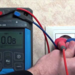
- Before connecting the device to the circuit under test, check for voltage and residual charge with a voltmeter.
How to ensure safe handling of the megohmmeter
Work is only performed with megohmmeters that are in good working order (tested and verified under the conditions of a specially designated metrology laboratory). Verification allows the owner of the unit to possess a special certificate, which gives a time-limited right to work, that is, until a certain period of validity. After verification, the specialist puts a stamp on the body of the unit, which indicates that the verification was carried out. The branding contains the date and number of the verification. It is the responsibility of the owner of the megohmmeter to maintain the integrity of the seal, because it gives the right to conduct subsequent measurements. If there is no label, the instrument is defective!
When making several measurements in a row in a ten-core cable, a portable earth ground should be used at all times and the residual charge should be removed after each measurement. Quick and safe operation of the megohmmeter is ensured by connecting one end of the grounding conductor to the grounding circuit before all work is completed. The other end of the conductor is attached to an insulating rod, which is designed for easy reapplication of the grounding to safely remove the residual charge.
How do I connect a megohmmeter?
Each model of this instrument has a specified output voltage, so to effectively test the insulation or measure its resistance, it is necessary to select the correct megohmmeter.
To test cable insulation with a megohmmeter, create the so-called extreme case, in which the tested section is supplied with a voltage higher than the nominal, but within the allowable standards prescribed in the technical documentation.
For example: a megohmmeter generator can deliver:
- 100V;
- 250V;
- 500V;
- 700V;
- 1000V;
- 2500V.
Accordingly the voltage supply should be an order of magnitude greater.
The duration of the measurement process usually does not exceed 30 seconds or a minute, this is necessary for more accurate detection of defects, as well as to exclude their subsequent occurrence in case of voltage drops in the network.
The basis of the technological process of resistance measurement is as follows: preparation to the process, its performance and the final stage. Each of them includes a certain list of manipulations necessary to achieve the set goal without harming others and, first of all, oneself.
When preparing for work, you should organize your actions, study the circuit diagram of the electrical installation in order to avoid possible damage and to ensure your safety.
Starting work, you should first check the device for proper operation. To do this, the leads are connected to the measurement wires. Then their ends are connected to each other trying to short-circuit. After applying the voltage, the measurement readings are measured (they must be equal to zero). The next step is to measure again. If there are no faults, the reading should be different from the previous one.
Then connect the portable grounding to the ground loop, check and ensure that there is no voltage on the site, set the portable grounding, assemble the measuring circuit of the device, remove the portable voltage, remove the residual charge, disconnect the connecting wire, remove the portable voltage.
The final stage involves restoring the disassembled circuits, removing shunts and shorts, as well as preparing the circuit to the operating mode. Document the obtained results of measuring the insulation layer resistance in the act of insulation verification.
Related articles: