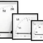
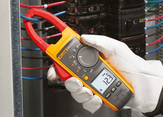
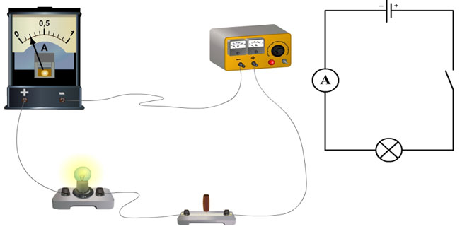
Measuring the amount of electricity that has passed in a unit of time through a cross section of a conductor (current intensity - I) is traditionally carried out when a circuit is broken with a special device connected at this moment, which makes the measurement. Current clamps are used to determine the intensity of an electromagnetic field occurring near a conductor. Their use speeds up and simplifies the measurement process.
Contents
What do clamp meters measure?
Before you buy this device, you must decide for what purpose the clamp meter is intended.
They are a transformer with an ammeter connected. The device itself is the transformer's primary winding. Placing a conductor inside it helps induce an electric current onto the winding due to the resulting electromagnetic field. It then enters the secondary winding of the coil, which is read by the ammeter. The readings of this device are recalculated with a correction to the transformation ratio indicated on it. The transformer does not work with direct current, so the current clamps described are for alternating current.
Electro-measuring clamps made today are used for values measured at direct current. A Hall sensor is placed in place of the ammeter to detect the presence and voltage of an electromagnetic field.
Using these instruments, the following measurements are made:
- The load of the mains available on the actual load;
- Accuracy of readings of various equipment designed for electricity metering by comparing the readings on them with the readings obtained by measuring with clamp meters;
- The power of household and professional electrical appliances.
DC current clamps are more expensive than their AC counterparts, but they are more accurate and have better quality indicators.
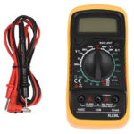
The tool, used in conjunction with a digital multimeter, saves the user the trouble of calculating the desired value, because the device has a built-in calculator.
Principle of operation of the clamp meter
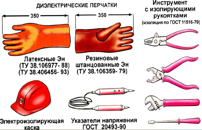
When using any method the basic principle is measurement. It is the same whether the multimeter is used for everyday use (up to 1000 V) or for professional use (above 1000 V). Household clamp meters are one-handed and professional clamp meters are mostly two-handed. It makes sense to purchase professional instruments when working with high-voltage networks.
Electrical clamp meters connected to a multimeter allow you to measure in the following sequence
- the wire to measure the electric current is detected (the tool's girth around several wires during the measurement contributes to an incorrect result);
- select the range and mode of the tester - if the value of I is unknown, the measurements start with the largest scale;
- place in the current clamps the conductor in which you want to measure I (to achieve an accurate measurement the wire is placed perpendicular to the center relative to the body of the device).
The measurement mode is automatic, the figures are shown on the display.
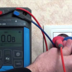
Using a simple example we can demonstrate how to check the load in the 220 V mains. The switch position of the clamps in order to measure the current is AC 200, the clamps embrace the conductor, and then take the reading. The product of the measured value and the voltage is found. The calculated value can be compared to the values from the electricity meter.
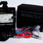
Components of a clamp meter
Electric clamp meters have the following basic elements:
- connectors, into which the corresponding probes are connected;
- The display, which shows the result of the measurement;
- mode switch;
- tool release button;
- magnet wire (the pliers themselves).
When measuring direct current the instrument scheme includes:
- electric current transformer;
- rectifying bridge.
The secondary winding is connected to the keys by a set of shunts.
Current clamps are subdivided into one- and two-handed. One-handed tongs combine a handle and an insulating part. The opening is done with a pushing lever. Work is done with one hand.
Two-handed devices have handles larger than 13 cm, and the insulating part is 38 cm or more. A design feature is their use with 2 hands.
When buying determine how to choose the right tool. In retail outlets there is a large assortment of these devices with different functionality, on which the price depends. When buying, the consumer must decide on the necessary functionality, some of which may be unnecessary.
Basically, the tool is designed to do the following tasks:
- measure the mains voltage and give out amperes;
- determine the frequency of electric current;
- test wires.
Measuring Modes
There are 2 methods of determining the amperage:
- direct;
- Indirect (inductive) measurement.
The first method is performed by connecting an ammeter to an open circuit. Electric current flows through the device, information about the value of I appears on the display.
The advantages of this method are:
- Accuracy of measurement, depending on the class of equipment;
- ease and accessibility of making measurements.
Disadvantages:
- it is impossible to measure large values of electric currents due to the design features;
- It is impossible to measure the parameters of a circuit without interruption;
- measurements are made only in the circuit that is connected to the device.
If the clamp meter acts as a current transformer in the role of the secondary coil, then the inductive method is used.
Its advantages are:
- safety;
- Large values of electricity can be measured;
- No need to break the circuit to make measurements;
- mobility of performed measurements.
But it is not without disadvantages:
- measurements cannot be made in hard-to-reach places;
- at small values of the determined parameters - a large error.
When using this tool for the electrician it is useful to know some nuances that improve the quality of the operations.
When considering how to use the current-measuring pliers when the value of I in the conductor is too small, not determined by the tester in accuracy, you need to use the winding of the conductor on one of the working parts of the device. The display shows the total value, the exact value is determined by the ratio of the obtained value to the number of turns.
If the value of the electric current is higher than the maximum possible value for the tester, "1" appears on the screen. The range of the measurements to be made is increased, they are repeated.
The leakage current is detected by looking for it on the ground wire, as well as when the clamp meter is used to measure the zero and phase currents. If a number other than "0" appears on the screen, then the leakage is present, the insulation breakdown should be looked for on the body.
With the "Hold" button, the model of current clamps can measure electrical current in hard-to-reach places. In making such an action, the current clamp covers the wire, then this button is pressed, which causes the value to be fixed on the screen, after which it is viewed in any accessible location.
The measurement mode switch can be in different positions depending on which value is being measured. Thus, when determining the direct current it is placed in the "DCA" position, and the voltage - "DCV", for alternating types - "ACA" and "ACV" respectively. Also, the switch allows you to carry out a test, check diodes and resistance.
The probes are connected through different-colored connectors that have different alpha-symbol designations. The red wire is connected to the same connector labeled "VΩ". The same color "EXT" connector is used to connect the insulation meter. The neutral wire is connected to the same color connector labeled "COM".
Safety precautions during operation
Interaction with any devices that come into contact with electricity requires observance of certain safety measures. The pliers in question are no exception. During active operations carried out by them, it is forbidden:
- when they are connected to the current-carrying elements to touch the open connectors;
- measure resistance when working under voltage;
- switch ranges when a conductor is in the tool;
- exceed the maximum overload capacity of the tool for a certain range.
Work with professional tools in electrical installations with voltages above 1000 V is carried out by 2 workers: 1 with Group III and 1 with Group IV.