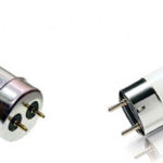
Fluorescent lamps are based on the glow of a gas discharge in mercury vapor. The radiation is in the ultraviolet range and to convert it into visible light, the lamp bulb is covered with a layer of phosphor.
Contents
Principle of operation of a fluorescent lamp
The peculiarity of fluorescent luminaires is that they cannot be directly connected to the power grid. The resistance between the electrodes when cold is high and the current flowing between them is insufficient to generate a discharge. A high voltage pulse is required for ignition.
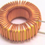
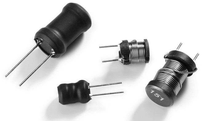
The lamp with the ignited discharge is characterized by a low resistance, which has a reactive characteristic. To compensate for the reactive component and to limit the current flow, a choke (ballast) is connected in series with the fluorescent light source.
Many people don't understand why a starter is needed in fluorescent lamps. The choke, included in the power circuit together with the starter, forms a high voltage pulse to start the discharge between the electrodes. It does this because the self-induction pulse of up to 1kV is generated at the terminals of the choke when the starter contacts open.
What the choke is used for
The use of a choke for fluorescent lamps (ballast) in power circuits is necessary for two reasons:
- To form the starting voltage;
- limiting the current through the electrodes.
The principle of the choke is based on the reactance of the inductance coil, which is the choke. The inductive resistance introduces a phase shift of 90º between voltage and current.
Since the current limiting value is the inductive resistance, it follows that chokes designed for lamps of the same power cannot be used to connect more or less powerful devices.
Within certain limits, tolerances are possible. For example, previously the domestic industry produced fluorescent lamps with a power of 40W. Choke 36W for fluorescent lamps of modern production can be used without fear in the power circuits of obsolete lamps and vice versa.
Differences between the choke and EB
Throttle circuit connection of fluorescent light sources is characterized by simplicity and high reliability. The exception is the regular replacement of starters, because they include a group of disconnecting contacts to form trigger pulses.
At the same time, the scheme has significant disadvantages, which have forced the search for new solutions for switching on the lamps:
- long start-up time, which increases as the lamp wears out or the supply voltage decreases;
- large distortions of the supply voltage waveform (cosf<0.5);
- flicker glow at twice the frequency of the supply network due to the low inertia of the luminosity of the gas discharge;
- large mass-dimensional characteristics;
- low-frequency hum due to vibration of plates of magnetic system of the throttle;
- low starting reliability at negative temperatures.
Checking the choke of daylight lamps is complicated by the fact that devices to determine short-circuited turns are not widespread, and using standard devices can only state the presence or absence of a breakage.
To eliminate these shortcomings, electronic ballasts (EBs) have been developed. Electronic circuits are based on a different principle of generating high voltage start and maintain combustion.
The high-voltage pulse is generated by electronic components, and a high-frequency voltage (25-100 kHz) is used to support the discharge. The ECG can be operated in two modes:
- with electrode preheating;
- with cold start.
In the first mode, low voltage is applied to the electrodes for 0.5-1 second for initial heating. After the time has elapsed, a high-voltage pulse is applied, which causes the ignition of a discharge between the electrodes. This mode is technically more complicated, but increases the life of the lamps.
The cold start mode is different in that the starting voltage is applied to the unheated electrodes, causing a quick turn-on. This starting mode is not recommended for frequent use because it greatly reduces the service life, but it can be used even with lamps with faulty electrodes (with burned-out filaments).
Circuits with an electronic choke have the following advantages
- complete absence of flicker;
- wide temperature range of use;
- small distortions of line voltage shape;
- absence of acoustic noise;
- increased service life of light sources;
- small size and weight, possibility of miniature design;
- possibility of dimming - changing the brightness by controlling the pulse width of the electrodes.
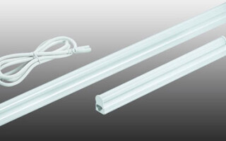
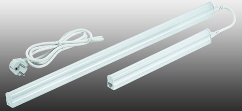
Classic connection via electromagnetic ballast - choke
The most common circuit for connecting a fluorescent lamp includes a choke and starter, which are called electromagnetic ballast (EmPRA). The circuit is a chain: choke - filament - starter.
At the initial moment of switching on, a current flows through the circuit elements which heats up the filament of the lamp and at the same time the contact group of the starter. After the contacts are heated, they open, provoking the appearance of self-induction EMF at the ends of the electromagnetic ballast winding. The high voltage causes a breakdown of the gas gap between the electrodes.
A low capacity capacitor connected in parallel to the starter contacts forms an oscillating circuit with the choke. This solution increases the value of the starting pulse voltage and reduces the burning of the starter contacts.
When a steady discharge occurs, the resistance between the electrodes at opposite ends of the bulb drops and current flows through the choke-electrode circuit. The current at this time is limited by the inductive resistance of the choke. The electrode in the starter closes, the starter at this time is no longer involved in the work.
If the discharge in the bulb did not occur, the heating and ignition process is repeated several times. During this time, the lamp may flicker. If the fluorescent lamp flickers but does not light up, it may indicate a failure of the lamp as a result of a decrease in the emissivity of the electrodes or a low voltage supply.
The connection of fluorescent lamps with a choke can be supplemented with a capacitor that reduces mains distortion. A capacitor is also installed in twin luminaires to shift the lights between neighboring lamps to visually reduce the flicker effect.
Connection via modern electronic ballast
In luminaires that use electronic ballasts for operation, the wiring diagram for fluorescent lamps is shown on the ECG casing. To switch on correctly, the instructions must be followed exactly. No adjustments are required. Correctly assembled circuit with serviceable elements begins to work immediately.
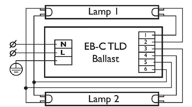
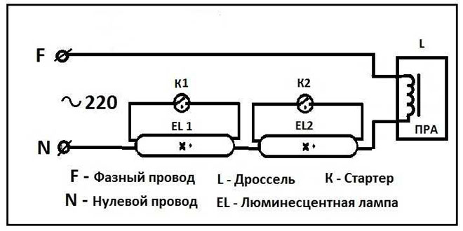
Diagram for connecting two lamps in series
Fluorescent lamps are allowed to connect two lighting devices in series in one circuit under the following conditions:
- the use of two identical light sources;
- electromagnetic ballast designed for a similar circuit;
- a choke designed for twice the power.
The advantage of the series circuit is that only one heavy choke is used, but if one of the bulbs or the starter fails, the luminaire is completely inoperable.
Modern EBs allow switching only according to this scheme, but many designs are designed to switch on two lamps. The circuit has two independent voltage shaping channels, so the dual electronic ballast ensures that one lamp will work if the adjacent one fails or is absent.
Connection without starter
Several options have been developed for switching on fluorescent lights without a choke and starter. All use the principle of creating a high starting voltage with a voltage multiplier.
Many of the circuits allow operation with blown filaments, allowing faulty lamps to be used. Some solutions use DC power. This results in no flicker at all, but the electrodes wear out unevenly. This can be noticed by the presence of dark spots of phosphor on one side of the bulb.
Some electricians install a separate start button instead of the starter, but it implies controlling the switching of the lamp with a switch and a button, which is inconvenient and may damage the lamp if the button is pressed too long because of overheated electrodes.
The schemes of switching on the fluorescent luminaires without using a starter, except for EBRA, are not produced by the industry. This is due to their low reliability, the negative impact on the life of the lamps, large size due to the presence of high-capacity capacitors.
Related articles: