To check the condition of the car batteryCar battery is not necessary to have professional equipment, industrial stands, etc. All the necessary and sufficient information for the car owner can be obtained with multimeter and a few additional items that can be found in a garage or auto store.
Contents
Battery charging level
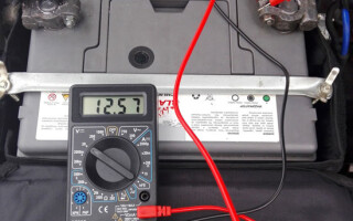
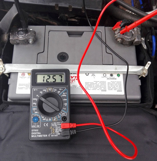
You can use the tester in voltmeter mode to check how much charge the battery has. The level of stored energy is unambiguously determined by the voltage at the battery terminals at idle:
- if the voltage is 12.6 volts or higher - the battery is 100;
- 12,3... 12,6 volt - 75% level of charge;
- 12,1...12,3 volt - 50%;
- 11,8...12,1 volt - 25%;
- 10,5...11,8 volt - battery is completely discharged;
- less than 10.5 volt - deeply discharged.
Before checking without removing from the car you must disconnect the plus terminal (and better the minus terminal, too).
Checking the actual battery capacity
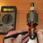
To measure such an important parameter as the real capacity of the battery battery capacity, you only need to have connecting wires and a load of known power (or known resistance) to the multimeter. For this purpose it is very convenient to use 12 volt car lamps:
- they are available at any auto store;
- you can dial up the battery to any desired power and set any discharge current.
In addition, the lamps as a load stabilize the current. When the voltage on the battery terminals decreases, the filaments cool down somewhat, their resistance decreases, and the decrease in current is negligible. This increases the accuracy of the measurement. But LED devices are not suitable for this purpose - they have too small power consumption, and you will need too many of them. You have to look for incandescent bulbs.
You should keep in mind that the capacity of depends on the current with which the battery is discharged. The declared capacity is declared when the battery is discharged with a current of 5% of the nominal value. It is necessary to choose the wattage of the lamps so as to get such a current. For example, for a battery with capacity of 60 A*h it is optimal to discharge with a current of 3 A for measurement. To do this, the power of the lamps at 12 volts should be P=U*I=12*3=36 watts. You can take three 12 watt lamps or two 18 watt lamps, etc. It is not necessary to be particularly precise - the exact capacitance is still unknown, it only has to be found out.
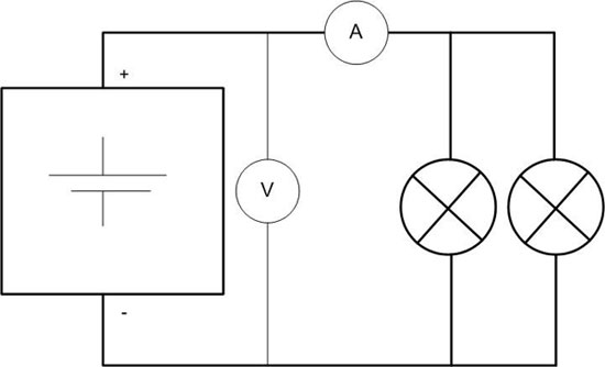
Before measuring it is necessary to fully charge the battery and assemble the circuit as shown in the figure. The time of the beginning of the discharge must be recorded. If you have two multimeters, you can measure current with one and voltage with the other, or you can periodically connect the tester as a voltmeter and as an ammeter. The results should be recorded every 30-60 minutes, and every 10-15 minutes when the voltage reaches 11.5 volts. When the voltage drops to 10.5 volts, you should stop discharging and record the time of its end. The real capacity is calculated by the formula C=I*t, where:
- I - averaged current in amperes;
- t - discharge time in hours.
So, if the battery was discharged for 16 hours with an average current of 3 amperes, its real capacity will be 16*3=48 A*h. Measurements must be taken at a temperature of +25 °C.
Measuring the current output of a battery
Theoretically, in this way you can measure the actual cold cranking current. According to the IEC standard (to which our GOST P 53165-2008) the measurement is made at the temperature of electrolyte minus 18 degrees, with terminal voltage decrease not lower than 8,4 volt. In practice, the problem is not only how to cool the battery to the desired temperature.
For example, for a battery with a declared current output of 600 amperes, a load of P=U*I=8,4*600=5000 watts will be required. Nowadays, high-power bulbs are produced mainly in LED version, and they are not suitable for our purposes, as stated above. If you use devices with power, for example, 60 watts, then they need in this case 84 pieces.
If you want to assemble a large daisy chain is possible, but there will be a problem of switching large currents so that the contacts when closing/opening the circuit are not welded. You can adapt a pullup relay from a car starter for this purpose. You will also have to find a tester with DC clamps (and such devices are less common and more expensive than AC meters) and with a measurement limit of several hundred amperes. In addition, the measurement will not last long, so you should make sure that the multimeter has a function for fixing the peak value.
Measuring the internal resistance of a battery
With this circuit you can measure the internal resistance of the battery. It can be conventionally represented as a resistor connected to the battery terminals from the inside.
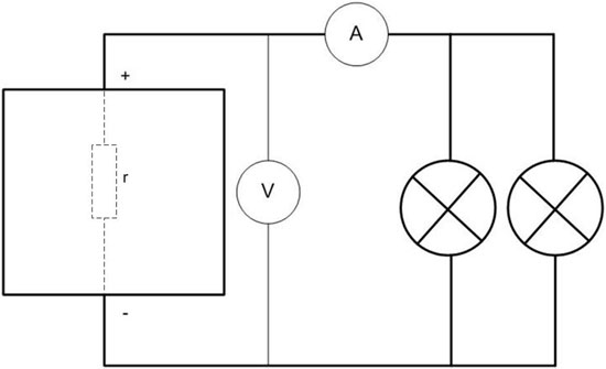
To increase the accuracy it is necessary to take a heavier load so that the current is not less than 50 amperes (or better 100 or more). For this purpose, a "battery" of lamps with total power not less than P=U*I=12*50=600 watt is suitable. If you get more, the measurement will be more accurate. Instead of lamps, you can use a resistor made, for example, from a spiral for an iron or electric stove. You just need to measure its resistance accurately. Two measurements are made:
- at idle, fix the voltage on the battery terminals E;
- under load measure the current I and the voltage on the terminals U.
Measurement under load is carried out once, a few seconds is enough. Then you have to use Ohm's law for a complete circuit:
I=E*(R+r),
hence
r=I/E-R,
where:
- E - battery EMF in volts, with certain assumptions equal to the open circuit voltage of the battery;
- I - measured current in amperes;
- R - external load resistance, ohm.
- r - required internal resistance, Ohm.
Voltage at the terminals under load will allow to calculate the load resistance (together with the connecting wires), if it is not known (and even if it is known, it will change when heated by high current during the experiment). It is equal to R=U/I.
The hardest part is how to interpret the result. The lower the internal resistance, the more current the battery will deliver to the load. But it is not clear what resistance is considered normal, because the manufacturers do not specify this value either on the battery nameplate, or in the accompanying technical documentation. And in this there is a logic, because the internal resistance is a very non-linear function of many things:
- temperature;
- the composition of the electrolyte;
- the battery's degree of charge;
- other factors.
These conditions are difficult to observe in a garage or even in a factory. You can only go by the value of a few milliom for a new battery with a good current output. Or accumulate statistics by measuring many batteries of the same type, whose condition is known.
Such a measurement is made with a load fork. Only in this kind of testing, the internal resistance is not calculated, and based on the results of two measurements (with open circuit and under load) a conclusion about the performance of the battery is made according to the table.
Checking the mode of operation as part of the electrical equipment of the car
Also a multimeter comes in handy to check the operation of the battery "on board". First of all, you can determine whether the battery is charged when the alternator is running.
To do this, the condition that the on-board voltage exceeds the battery voltage must be met, in which case the current will "flow" into the battery. First measure the voltage across the battery terminals with the engine turned off. It should be from 10.5 to 12.6 volts (depending on the battery charge level). Then you must start the engine with a normally working alternator and the voltage should increase to at least 14...14.5 volts. If the voltage is lower, you should look for a faulty alternator. Both checks should be made with disconnected powerful consumers (lights, car audio, heating devices, etc.).
You can also use the tester to determine the presence of current leaks while the car is parked. For this purpose, it is very convenient to use a tester with DC clamps. It is necessary to turn off the engine and disconnect all on-board power consumers, as far as possible. If you measure the current on e.g. the plus wire from the battery, the ammeter should show a value close to zero or a current similar to the consumption of loads that could not be disconnected. If the measurement result is higher, you should look for the problem.
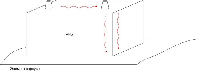
It should be remembered that if the leakage current goes through a layer of contamination on the battery case, you can not find it this way - the path of current flow will pass by the plus wire. Therefore it makes sense to clean the battery from dirt beforehand, having washed it with warm water and detergents.
As a result, having multimeter and some knowledge, you can determine not only the actual state of the battery, but also its mode of operation. It is not difficult, and will help to avoid significant monetary expenses.
Related articles: