Electrical capacitance is one of the basic concepts of electrostatics. This term refers to the ability to accumulate an electrical charge. You can talk about the capacitance of a single conductor, you can talk about the capacitance of a system of two or more conductors. The physical processes are similar.

Contents
Basic concepts related to capacitance
If a conductor has received a charge q, a potential φ arises on it. This potential depends on the geometry and environment - for different conductors and conditions, the same charge will cause a different potential. But φ is always proportional to q:
φ=Cq
The coefficient C and is called the electrical capacitance. If we are talking about a system of several conductors (usually two), when a charge is given to one conductor (cladding), there is a potential difference or voltage U:
U=Cq, hence C=U/q
Capacitance can be defined as the ratio of the potential difference to the charge that caused it. The unit of capacity in the SI is the Farad (they used to say Farad). 1 F = 1 V/1 Cl. In other words, a system in which a charge of 1 coulomb gives rise to a potential difference of 1 volt has a capacity of 1 farad. 1 Farad is a very large value. In practice, fractional values - picofarads, nanofarads, microfarads - are most commonly used.
In practice, this connection allows for a battery that can withstand a higher dielectric breakdown voltage than a single cell.
Calculation of capacitor capacity
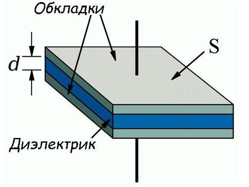
In practice, as elements with normalized electrical capacitance, the most commonly used are capacitors, consisting of two flat conductors (terminals), separated by a dielectric. The formula for calculating the electrical capacitance of such a capacitor is as follows:
C=(S/d)*ε*ε0
where:
- C is the capacitance, F;
- S is the area of the inserts, sq.m;
- d is the distance between the covers, m;
- ε0 - electrical constant, constant, 8.854*10−12 F/m;
- ε - dielectric permittivity, dimensionless value.
From this it is easy to understand that the capacitance is directly proportional to the area of the covers and inversely proportional to the distance between the conductors. The capacitance is also affected by the material with which the covers are separated.
To understand how the quantities that determine capacitance affect a capacitor's ability to store a charge, you can do a mental experiment to create a capacitor with the highest possible capacitance.
- You can try to increase the area of the windings. This will lead to a dramatic increase in the size and weight of the device. In order to reduce the size of the layers with the dielectric separating them, they are rolled up (into a tube, flat briquette, etc.).
- Another way is to reduce the distance between the covers. It is not always possible to place the conductors very close to each other, because the dielectric layer must be able to withstand a certain potential difference between the covers. The smaller the thickness, the lower the electrical strength of the insulating gap. If we use this way, there will come a moment when the practical application of such a capacitor becomes meaningless - it can work only at extremely low voltages.
- Increasing the dielectric electrical permeability. This way depends on the development of current production technology. The insulating material must have not only a high permeability value, but also good dielectric properties, and retain its parameters in the required frequency range (as the frequency at which the capacitor operates increases, the dielectric characteristics decrease).
Spherical or cylindrical capacitors can be used in some specialized or research installations.
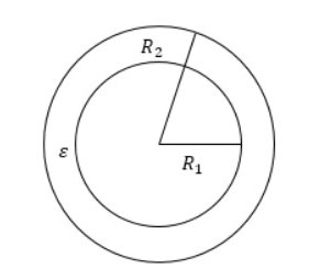
The capacity of a spherical capacitor can be calculated by the formula
C=4*π*ε0 *R1R2/(R2-R1)
where R is the radii of the spheres and π=3.14.
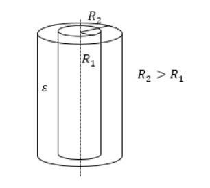
For a cylindrical capacitor design, the capacitance is calculated as:
C=2*π*ε*ε0 *l/ln(R2/R1)
l is the height of the cylinders, and R1 and R2 are their radii.
In principle, both formulas do not differ from the formula for a flat capacitor. The capacitance is always determined by the linear dimensions of the terminals, the distance between them, and the properties of the dielectric.
Connecting capacitors in series and parallel
Capacitors can be connected in series or in parallel, creating a set with new characteristics.
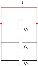
Parallel connection
If the capacitors are connected in parallel, the total capacitance of the resulting battery is equal to the sum of all the capacitances of its components. If a battery consists of capacitors of the same design, it can be thought of as adding up the area of all the plates. In this case, the voltage on each element of the battery will be the same and the charges will add up. For three capacitors connected in parallel:
- U=U1=U2=U3;
- q=q1+q2+q3;
- C=C1+C2+C3.
Connection in series
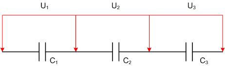
When connected in series, the charges of each capacitance will be the same:
q1=q2=q3=q
The total voltage is distributed in proportion to to the capacitance of the capacitors:
- U1=q/ C1;
- U2=q/ C2;
- U3= q/ C3.
If all capacitors are the same, then the same voltage falls on each. The total capacitance is found as:
C=q/( U1+U2+U3), hence 1/C=( U1+U2+U3)/q=1/C1+1/С2+1/С3.
Applications of capacitors in engineering
It makes sense to use capacitors as accumulators of electrical energy. As such, they cannot compete with electrochemical sources (galvanic batteries, capacitors) due to small stored energy and rather rapid self-discharge due to charge leakage through the dielectric. But their ability to store energy for a long period and then give it away almost instantly is widely used. This property is used in flash lamps for photography or in lamps for excitation of lasers.
Capacitors are very common in radio engineering and electronics. Capacitors are used in resonant circuits as one of the frequency-retaining elements of circuits (another element is inductance). The ability of capacitors to keep out direct current without trapping the AC component is also used. Such an application is common for dividing amplifier stages to eliminate the influence of the DC modes of one stage on the other. High-capacity capacitors are used as smoothing filters in power supplies. There are also a myriad of other capacitor applications where their properties prove useful.
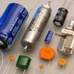
Some practical capacitor designs
A variety of flat capacitor designs are used in practice. The design of the device determines its characteristics and application.
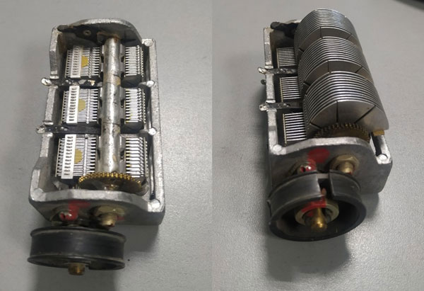
Variable capacitor
A common type of variable capacitor (AC capacitor) consists of a block of movable and fixed plates separated by air or a solid insulator. The movable plates rotate around an axis, increasing or decreasing the overlapping area. When the movable unit is withdrawn, the interelectrode gap remains unchanged, but the average distance between the plates also increases. The dielectric constant of the insulator also remains unchanged. The capacitance is adjusted by changing the area of the covers and the average distance between them.
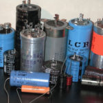
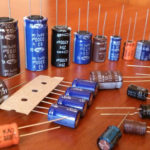
Oxide capacitor
This type of capacitor used to be called an electrolytic capacitor. It consists of two strips of foil separated by a paper dielectric soaked in electrolyte. The first strip serves as one cover and the second as the electrolyte. The dielectric is a thin layer of oxide on one of the metal strips, and the second strip serves as the current collector.
Because the oxide layer is very thin and the electrolyte is close to it, it was possible to get quite large capacities with moderate size. The price for this is the low operating voltage - the oxide layer does not have a high electrical strength. As the operating voltage increases, the size of the capacitor has to increase significantly.
Another problem is that the oxide has a one-way conductivity, so such capacitors are used only in DC circuits with observance of polarity.
Ionistor
As shown above, traditional methods of increasing capacitors have natural limitations. Therefore, the real breakthrough was the creation of ionistors.
Although this device is considered to be an intermediate between a capacitor and a battery, it is still essentially a capacitor.
The distance between the coils is drastically reduced through the use of a double electric layer. Layers of ions with opposite charges serve as the layers. It is possible to drastically increase the surface area of the covers due to the foam porous materials. As a result, it is possible to obtain supercapacitors with capacities up to hundreds of farads. The inherent disease of such devices is low operating voltage (usually within 10 volts).
The development of technology does not stand still - lamps from many areas have been replaced by bipolar transistors, they, in turn, are replaced by unipolar triodes. The inductors are getting rid of in circuit design wherever possible. And capacitors do not give up their positions for the second century, their design has not changed fundamentally since the invention of the Leiden jar, and the prospects for the end of their career is not observed.
Related articles: