Inductance is a measure of the ability of components in an electrical circuit to store magnetic field energy. It is also a measure of the relationship between current and magnetic field. It is also compared to the inertia of electricity, as mass is a measure of the inertia of mechanical bodies.
Contents
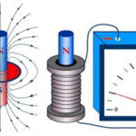
The phenomenon of self-induction
If the current flowing through a conducting circuit varies in magnitude, the phenomenon of self-induction occurs. In this case, the magnetic flux through the circuit changes, and an EMF called the self-induction EMF arises at the leads of the current frame. This EMF is opposite to the direction of the current and is equal to:
ε=-∆F/∆t=-L*(∆I/∆t)
Obviously, the self-induction EMF is equal to the rate of change in magnetic flux caused by the change in current flowing through the circuit, and is also proportional to the rate of change in current. The coefficient of proportionality between the EMF of self-induction and the rate of change of current is called inductance and is denoted by L. This value is always positive, and has a SI unit of 1 Henry (1 Gn). Fractional fractions, milligeneries and microgeneries, are also used. We can speak of an inductance of 1 Henry if a change in current of 1 ampere causes an EMF of 1 volt of self-induction. Not only a circuit has inductance, but also a single conductor and a coil, which can be represented as a set of circuits in series.
Energy is stored in the inductance, which can be calculated as W=L*I2/2, where:
- W - energy, J;
- L - inductance, Gn;
- I - current in the coil, A.
And here the energy is directly proportional to the inductance of the coil.
Important! In engineering, inductance also refers to the device in which the electric field is stored. The real element closest to this definition is an inductor coil.
The general formula for calculating the inductance of a physical coil has a complicated form and is inconvenient for practical calculations. It is useful to remember that the inductance is proportional to the number of turns, the diameter of the coil and depends on the geometric shape. Also the inductance is affected by the magnetic permeability of the core on which the coil is located, but is not affected by the current flowing through the coils. In order to calculate the inductance, each time you have to refer to the given formulas for a particular design. Thus, for a cylindrical coil, its basic characteristic is calculated according to the formula:
L=μ*μ*(N2*S/l),
Where:
- μ is the relative magnetic permeability of the coil core;
- μ - magnetic constant, 1.26*10-6 Gn/m;
- N - number of turns;
- S - area of coil;
- l - geometric length of the coil.
To calculate the inductance for a cylindrical coil and other coil shapes, it is better to use calculator programs, including online calculators.
Connecting inductances in series and parallel
Inductances can be connected in series or parallel, producing a set with new characteristics.
Parallel connection
When coils are connected in parallel, the voltages on all elements are equal and the currents (alternating) are inversely proportional to the inductances of the elements.
- U=U1=U2=U3;
- I=I1+I2+I3.
The total inductance of the circuit is defined as 1/L=1/L1+1/L2+1/L3. The formula is valid for any number of elements, and for two coils it is simplified to the form L=L1*L2/(L1+L2). It is obvious that the resulting inductance is less than the inductance of the element with the lowest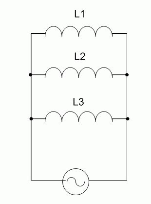
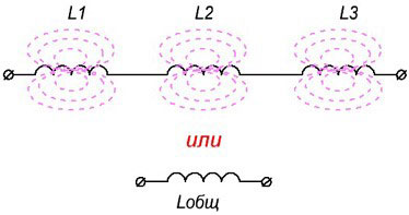
Series connection
With this type of connection, the same current flows through a circuit made up of coils, and the voltage (AC!) on each component of the circuit is distributed in proportion to the inductance of each element:
- U=U1+U2+U3;
- I=I1=I2=I3.
The total inductance is equal to the sum of all inductances, and will be greater than the inductance of the element with the highest value. Therefore, this connection is used when it is necessary to obtain an increase in inductance.
Important! When connecting the coils in series or parallel battery, the calculation formulas are only true for cases where the mutual influence of the magnetic fields of the elements on each other is excluded (by shielding, large distance, etc.). If the influence exists, the total value of inductance will depend on the mutual arrangement of the coils.
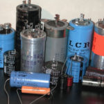
Some practical issues and designs of inductor coils
In practice various designs of inductor coils are used. Depending on the purpose and application of the device can be made in different ways, but it is necessary to consider the effects occurring in real coils.
Quality factor of an inductor coil
A real coil has several parameters in addition to inductance, and one of the most important is the quality factor. This value determines the losses in the coil and depends on:
- ohmic losses in the winding wire (the greater the resistance, the lower the quality factor);
- Dielectric losses in the insulation of the wire and the frame of the winding;
- losses in the shield;
- Core losses.
All these quantities define the loss resistance, and the quality factor is a dimensionless value equal to Q=ωL/R loss, where:
- ω = 2*π*F - circular frequency;
- L - inductance;
- ωL - coil reactance.
We can roughly say that the quality factor is equal to the ratio of the reactive (inductive) resistance to the active resistance. On the one hand, with increasing frequency the numerator increases, but at the same time due to the skin effect the loss resistance also increases due to the reduction of the useful wire cross-section.
Skin effect
To reduce the influence of foreign objects as well as electric and magnetic fields and the mutual influence of elements through these fields, coils (especially high-frequency ones) are often placed in a shield. In addition to the useful effect, shielding causes a decrease in coil Q-factor, reducing its inductance and increasing the parasitic capacitance. Moreover, the closer the walls of the shield to the coil turns, the higher the harmful effect. Therefore, shielded coils are almost always made with the possibility of adjustment of parameters.
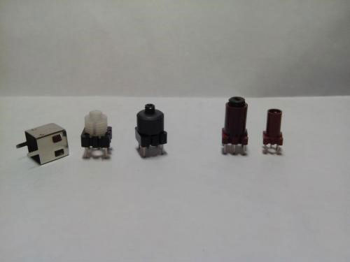
Adjustable inductance
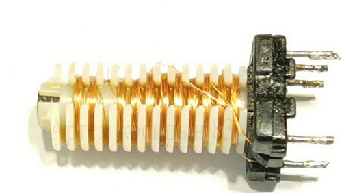
In some cases it is necessary to precisely set the inductance value in place after connecting the coil to other elements of the circuit, compensating for the deviation of the parameters during tuning. Different methods are used for this (switching of the turns, etc.), but the most accurate and smooth method is the adjustment with a core. It is made in the form of a threaded rod, which can be screwed in and out inside the frame, adjusting the inductance of the coil.
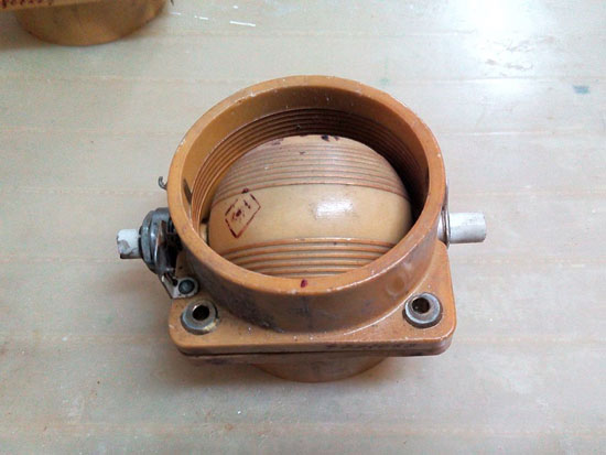
Variable inductance (variometer)
Where operational adjustment of inductance or inductive coupling is required, a different design of coil is used. They contain two windings, a moving winding and a stationary winding. The total inductance is equal to the sum of the inductances of the two coils and the mutual inductance between them.
By changing the relative position of one coil to the other, the total inductance value is adjusted. Such a device is called a variometer and is often used in communication equipment for tuning resonant circuits in cases where the use of capacitors of variable capacity for some reason is impossible. The variometer is quite cumbersome, which limits its area of application.
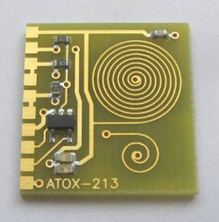
Inductance in the form of a printed coil
Coils with low inductance can be made in the form of a spiral of printed conductors. The advantages of such a design are:
- manufacturability;
- high repeatability of parameters.
The disadvantages are the impossibility of fine tuning during adjustment and the difficulty of obtaining large values of inductance - the higher the inductance, the more space the coil takes on the board.
Coil with sectional winding
Inductance without capacitance only happens on paper. With any physical implementation of a coil, there is immediately a parasitic inter-winding capacitance. This is in many cases a harmful phenomenon. The stray capacitance adds up to the capacitance of the LC-circuit, reducing the resonant frequency and the quality factor of the oscillating system. Also the coil has its own resonant frequency, which provokes undesirable phenomena.
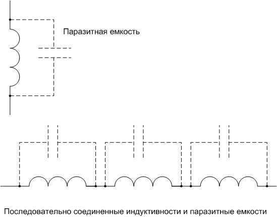
To reduce stray capacitance, various methods are used, the simplest of which is the winding of inductors in the form of several sections connected in series. With this connection, the inductances are added, and the total capacitance is reduced.
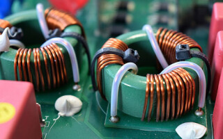
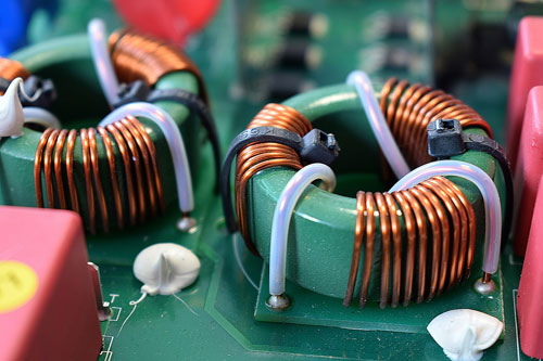
Inductance coil on a toroidal core
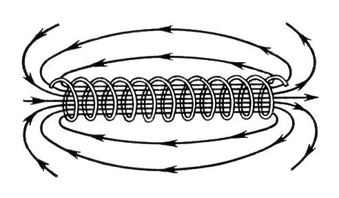
The magnetic field lines of a cylindrical inductor coil run through the inside of the coil (if there is a core, then through it) and are shorted out through the air. This fact entails several disadvantages:
- The inductance is reduced;
- the characteristics of the coil are less calculable;
- any object introduced into the external magnetic field changes the coil parameters (inductance, parasitic capacitance, losses, etc.), so in many cases shielding is required.
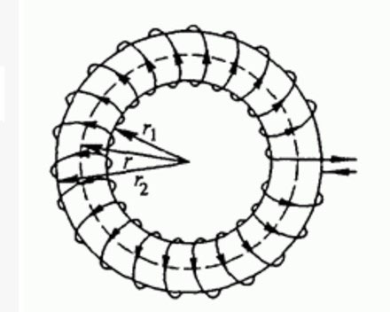
Coils wound on toroidal cores (in the form of a ring or "bagel") are largely free from these drawbacks. The magnetic lines run inside the core in the form of closed loops. This means that external objects have almost no effect on the parameters of a coil wound on such a core, and shielding is not necessary for such a design. Also, the inductance is increased, all other parameters being equal, and the characteristics are easier to calculate.
The disadvantages of coils wound on toruses include the inability to smoothly adjust the inductance in place. Another problem is the high labor intensity and low manufacturability of winding. However, this applies to all inductive elements in general, to a greater or lesser extent.
Also a common disadvantage of physical implementation of inductance are high mass dimensions, relatively low reliability and low maintainability.
Therefore, in technology, inductive components are tried to get rid of. But this is not always possible, so winding components will be used both in the foreseeable future and in the medium term.
Related articles: