Current transformers are widely used in today's energy industry as equipment for changing various electrical parameters while maintaining the basic values. The operation of the equipment is based on the law of induction, which is relevant for magnetic and electrical fields that change sinusoidally. The transformer transforms the primary value of the current with respect to the modulus and the angle transmission proportional to the raw data. It is necessary to select equipment based on the scope of use of the devices and the number of consumers connected.
Contents
What is a current transformer?
This equipment is used in industry, municipal communications and utilities, production and other areas to supply current with certain physical parameters. The voltage is applied to the coils of the primary winding, where an alternating current is generated as a result of magnetic radiation. The same radiation passes through the rest of the coils, due to which there is a movement of EMF forces, and when the secondary coils are shorted or when connected to the electric circuit, a secondary current appears in the system.
Modern current transformers make it possible to convert energy with such parameters, so that its use does not allow damage to the equipment, which operates on it. In addition, they make it possible to measure an increased load with maximum safety for machinery and personnel, because the coils of the primary and secondary rows have reliable insulation from each other.
What transformers for?
Determining what you need a current transformer for is quite simple: the scope of application includes all industries in which the transformation of energy quantities. These devices are among the auxiliary equipment, which is used in parallel with measuring instruments and relays in the creation of an alternating current circuit. In these cases, transformers convert energy to make it easier to decipher parameters or to connect equipment with different characteristics into a single circuit.
There is also a measuring function of transformers: they serve to start up electrical circuits with higher voltages, to which you want to connect measuring instruments, but it is not possible to do it directly. The main task of such transformers is to transmit the information obtained about the parameters of current to the instruments for measuring manipulation, which are connected to the secondary winding. Also the equipment gives the possibility to control the current in the circuit: when the relay is used and the maximum current parameters are reached, the protection is activated, switching off the equipment to avoid burnout and harm to personnel.
Principle of operation
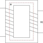
The action of such equipment is based on the law of induction, according to which the voltage hits the primary coils and the current overcomes the created winding resistance, which causes the formation of magnetic flux, transferred to the magnetic conductor. The flux is perpendicular to the current, which minimizes losses, and when it crosses the turns of the secondary winding, the EMF force is activated. As a result of its influence in the system there is a current that is stronger than the resistance of the coil, while the voltage at the output of the secondary coils is reduced.
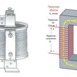
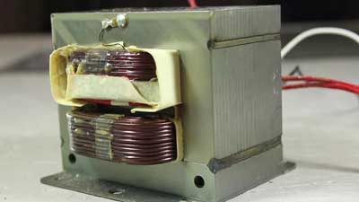
The simplest transformer design, therefore, includes a core of metal and a pair of windings, not connected to each other and made in the form of wiring with insulation. In some cases, the load only goes to the primary and not the secondary windings: this is the so-called idle mode. If power-consuming equipment is connected to the secondary winding, a current flows through the coils, which creates an electromotive force. The EMF parameters are determined by the number of turns. The ratio of the electromotive force for the primary and secondary turns is known as the transformation ratio, calculated by the ratio of their number. It is possible to regulate the end-user voltage by changing the number of primary or secondary turns.
Classification of current transformers
There are several types of such equipment, which are divided according to a number of criteria, including purpose, method of installation, the number of conversion stages and other factors. Before selecting a current transformer, you need to consider these parameters:
- Purpose. According to this criterion, there are measuring, intermediate and protective models. For example, devices of intermediate type are used when connecting devices for computational actions in relay protection systems and other circuits. Separately allocated laboratory transformers, which provide increased accuracy of indicators, have a large number of conversion coefficients.
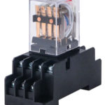
- Installation method. There are transformers for external and internal installation: they not only look different, but also have different indicators of resistance to external influences (for example, devices for outdoor use have protection against precipitation and temperature differences). Also distinguish overhead and portable transformers; the latter have a relatively low weight and dimensions.
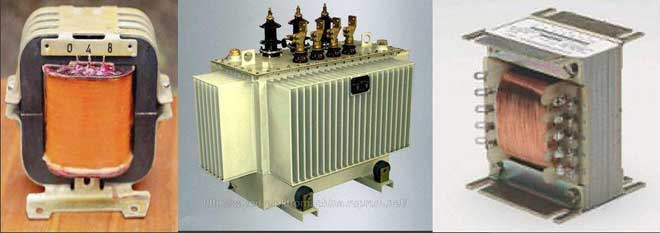
- Type of winding. Transformers can be single- and multi-coil, coil, rod, busbar. Both primary and secondary windings can be different, and the differences are also related to insulation (dry, porcelain, Bakelite, oil, compound, etc.).
- Level of transformation steps. The equipment can be single-stage or two-stage (cascade), the voltage limit of 1000 V can be minimum or, on the contrary, maximum.
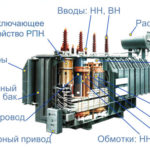
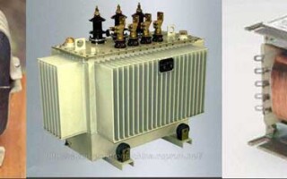
- Design. According to this criterion, there are two varieties of current transformers - oil-type and dry-type. In the first case, the turns of the winding and the magnetic core are in a vessel containing a special oily liquid: it plays the role of insulation and allows the regulation of the working temperature of the medium. In the second case, the cooling is air-cooled, such systems are used in industrial and residential buildings, as oil transformers cannot be installed inside due to increased fire hazard.
- Type of voltage. Transformers can be step-down and step-up: in the first case, the voltage on the primary windings is reduced, and in the second - increased.
- Another option for classification is the choice of current transformer by power. This parameter depends on the purpose of the equipment, the number of connected consumers, their properties.
Parameters and characteristics
When choosing such equipment, you need to consider the main technical parameters affecting the range of application and cost. The main qualities are:
- Nominal load, or power: selection according to this criterion can be made by using a comparative table of transformer characteristics. The value of the parameter determines the other current characteristics, since it is strictly standardized and serves to determine the normal functioning of the equipment in the selected accuracy class.
- Rated current. This parameter determines for how long the device can function without overheating to critical temperatures. Transformer equipment, as a rule, has a solid reserve on the level of heating, in case of overloading up to 18-20% the operation is normal.
- Voltage. This parameter is important for the quality of the winding insulation, it ensures trouble-free operation of the equipment.
- Error. This phenomenon occurs because of the effect of magnetic flux, the error value is the difference between the exact primary and secondary current data. Increasing the magnetic flux in the transformer core contributes to a proportional increase in error.
- The transformation ratio, which is the ratio of the current in the primary turns to the secondary turns. The real value of the coefficient differs from the nominal by an amount equal to the degree of energy conversion loss.
- Limit multiplicity, expressed as the ratio of the actual primary current to the nominal.
- Multiplicity of the current occurring in the turns of the secondary type winding.
The key data of the current transformer are determined by the substitution diagram: it allows you to study the characteristics of the equipment in different modes, from no-load to full-load.
The main indicators are marked on the body of the device in the form of a special marking. It can also contain data on the method of lifting and mounting of the equipment, warning information about high voltage on the secondary windings (over 350 volts), information about the presence of the grounding pad. The energy converter marking is applied in the form of a sticker or with paint.
Possible malfunctions
Like any other equipment, transformers malfunction from time to time and require expert service with diagnosis. Before you check the unit, you need to know what breakdowns occur and what signs correspond to them:
- Uneven noise inside the enclosure, crackling. This phenomenon usually indicates a breakage of the grounding element, an overlap to the case from the winding turns or a loose pressing of the sheets serving for the magnetic core.
- Excessive heating of the case, an increase in the current on the consumer side. The problem may be caused by winding short circuits due to wear or mechanical damage of the insulation layer, frequent overloads resulting from short circuits.
- Cracked insulators, sliding discharges. They appear in the case of manufacturing defects not detected before the start of operation, foreign objects, and overlap between phase inputs of different values.
- Oil emissions during which the diaphragm of the exhaust structure is destroyed. The problem is due to inter-phase short-circuiting caused by insulation wear, drop in oil level, voltage drop or overcurrent occurrence in the event of a through-type short-circuit.
- Oil fluid leaks from under gaskets or in transformer taps. The main causes are faulty welding of components, weak seals, destroyed gaskets or unrubbed tap plugs.
- Activation of gas protection relay. This phenomenon occurs when oil decomposition occurs due to a winding fault, circuit breakage, burnout of switch contacts, or in the case of a short circuit to the transformer housing.
- Gas protection relay tripping. Active decomposition of the oil liquid due to phase failure, internal or external overvoltage or due to a so-called "steel fire" causes the problem.
- Tripped differential protection. This fault occurs when there is a breakdown on the lead case, when there is overlap between phases, or in other cases.
In order to maximize the functionality of the device, regular calibration with a thermal imaging camera is required: the equipment allows you to diagnose a decrease in contact quality and a decrease in operating temperature. During verification the specialists perform the following range of manipulations:
- Taking readings on the voltage and current.
- Checking the load using an external source.
- Determination of the parameters in the operating circuit.
- Calculation of the transformation ratio, comparison and analysis of indicators.
Calculation of a transformer
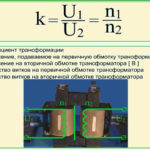
The basic principle of this device is defined by the formula U1/U2=n1/n2, the elements of which are deciphered as follows:
- U1 and U2 are the voltages of the primary and secondary turns.
- n1 and n2 are their number on the primary and secondary windings respectively.
To determine the cross-sectional area of the core, another formula is used: S=1,15 * √Pwhere power is measured in watts and area in square centimeters. If the core used in the equipment is in the shape of the letter Sch, the cross-sectional area is calculated for the middle core. When determining the turns in the primary level winding, the formula is applied n=50*U1/S, in this case the component 50 is not invariable, in calculations to prevent the occurrence of electromagnetic interference, it is recommended to put a value of 60 instead of it. Another formula is d=0,8*√Iin which d is the wire cross-section and I is the current strength index; it is used to calculate the cable diameter.
The figures obtained in the calculations are rounded up (e.g. the calculated power of 37.5 W is rounded down to 40). Rounding is only allowed upwards. All these formulas are used for selection of transformers, working in 220 V network; at construction of high-frequency lines other parameters and calculation methods are used.
Related articles: