Electromagnetic static devices are used to create and apply a magnetic field. There are many cases, why you need a transformer in electronic, electrical circuits and radio engineering. The device is equipped with inductive windings mutually connected on a magnetic core. The mains contributes to an alternating field, while the transformer uses electromagnetic induction to give constant values to the current without changing the frequency.
Contents
Definition and application
Various voltages of different characteristics are required to power devices. A transformer is a design for using the inductive operation of a magnetic field. Ribbon or wire coils connected by a common flux lower or increase the voltage. A television uses 5 volts to operate transistors and microcircuits, powering a kinescope requires several kilovolts when using a cascade oscillator.
Isolated windings are placed on a core of spontaneously magnetized material with a certain voltage value. Older units used the existing mains frequency, about 60 Hz. Modern appliance power circuits use high-frequency pulse transformers. The alternating voltage is rectified and converted by means of an oscillator to a value with specified parameters.
The voltage is stabilized by a control unit with pulse-width modulation. High-frequency bursts are transmitted to the transformer, the output receives stable values. The massiveness and heaviness of the devices of yesteryear is replaced by lightness and small size. The linear performance of the unit is proportional to the power in the ratio of 1:4, to reduce the size of the device increases the frequency of the current.
Massive devices are used in power supply circuits, if you want to create a minimum level of interference dissipation with high frequency, for example, when providing quality sound.
Design and principle of operation
The manufacturer chooses the basic rules of operation of the unit, but this does not affect the reliability of operation. The concepts differ in the manufacturing process. The principle of operation of the transformer is based on two statements:
- The changing motion of the directional charge carriers creates an alternating magnetic force field;
- The effect on the force flux transmitted through the coil produces an electromotive force and induction.
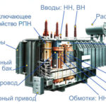
The device consists of the following parts:
- A magnetic conductor (core);
- coil or winding;
- a backbone for the arrangement of the coils;
- insulating material;
- cooling system;
- other elements of attachment, access, protection.
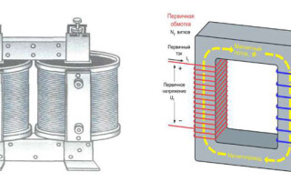
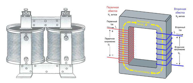
The operation of a transformer is based on the type of construction and combination of core and windings. In the core type, the conductor is enclosed in the windings and is difficult to see. The coils are visible, the top and bottom of the core are visible, and the axis is vertical. The material that makes up the coil must conduct electricity well.
In armored type products the core hides most of the turns, it is placed horizontally or plumb. Toroidal transformer design involves placing two independent windings on the magnetic core with no electrical connection between them.
Magnetic system
Made of alloyed transformer steel, ferrite, permalloy with preservation of the geometric shape to produce the magnetic field of the unit. The conductor is constructed of plates, tapes, horseshoes and it is made on a press. The part on which the winding is placed is called the yoke. The yoke is the element without coils, which performs the closing of the circuit.
The principle of operation of the transformer depends on the scheme of the struts, which are:
- flat - the axes of yokes and cores are in a single plane;
- spatial - longitudinal elements are arranged in different surfaces;
- symmetrical - conductors of the same shape, size and construction are arranged to all the yokes in a similar way to others;
- asymmetrical - individual stands differ in appearance, dimensions and are placed in different positions.
If it is assumed that a direct current flows through the winding, which is called the primary, the magnetic wire is made open. In other cases, the core is closed, it serves to close the power lines.
Windings
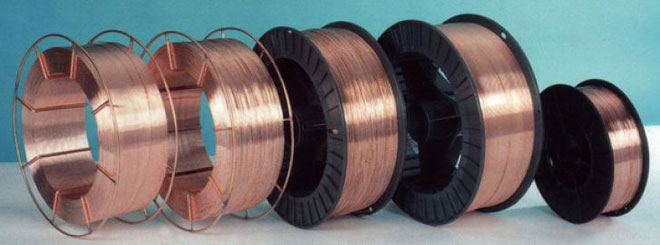
Made in the form of a set of turns, arranged on conductors with a square cross-section. The shape is used for efficient operation and to increase the fill factor in the window of the magnetic core. If it is necessary to increase the cross section of the core, it is made in the form of two parallel elements to reduce the occurrence of eddy currents. Each such conductor is called a core.
The core is wrapped in paper and coated with enamel varnish. Sometimes two cores arranged in parallel are encased in a common insulation, a set called a cable. The windings are differentiated according to their purpose:
- main - they are supplied with alternating current, the converted electric current comes out;
- regulating - they are provided with taps to transform the voltage at a low amperage
- auxiliary - they serve to supply their network with power less than the nominal indicator of the transformer and sub-magnetize the circuit with direct current.
Wrapping methods:
- Row winding - turns are made in the direction of the axis along the entire length of the conductor, the subsequent turns are wound tightly, without gaps;
- helical winding - multi-layer winding with gaps between the rings or bypassing the adjacent elements;
- disk winding - spiral row is performed sequentially, in a circle the winding is made in a radial order in the inner and outer direction;
- foil spiral is made of aluminum and copper wide sheet, which thickness varies from 0.1-2 mm.
Symbols
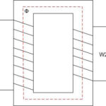
To make it easy to read the transformer diagram, there are special signs. The core is drawn with a thick line, the number 1 shows the primary winding, the secondary turns are indicated by numbers 2 and 3.
In some circuits, the core line is similar in thickness to the drawing of the half-circles of the coils. The designation of the core material is different:
- ferrite magnetic core is drawn with a thick line;
- steel core with magnetic gap is drawn with a thin line with a break in the middle;
- the axis made of magnetized dielectric is marked with a thin dotted line;
- copper rod is drawn as a narrow line with a material notation according to the Mendeleev's table.
Bold dots are used to highlight the coil output, the instantaneous induction designation is the same. Used to denote intermediate units in cascade generators to show the counter-phase. Put the dots if you want to set the polarity when assembling and the direction of the windings. The number of turns in the primary winding is defined conventionally, just as the number of half-circles is not normalized, there is proportionality, but it is not strictly observed.
Main characteristics
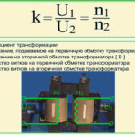
Idle mode is used when the transformer's secondary is open, there is no voltage in it. Current flows through the primary winding, and reactive magnetization occurs. Idle operation is used to determine efficiency, transformation ratio and core losses.
Load operation involves connecting the power supply to the primary circuit, where the total current of operation and no-load current flows. The load is connected to the secondary of the transformer. This mode is common.
The short-circuit phase occurs if the resistance of the secondary coil is the only load. In this mode the heating losses of the coil in the circuit are determined. The parameters of the transformers are taken into account in the device substitution system by means of the resistance setting.
The ratio of the input and output power determines the transformer's efficiency.
Applications
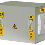
Household appliances have a ground connection via the neutral conductor. Consumers touching both the phase and neutral circuits at the same time will cause a loop fault and result in personal injury. Wiring through an isolating transformer keeps people safe because the secondary winding has no contact with ground.
Pulsed units are used when transmitting rectangular shocks and transforming short signals under load. The output changes the polarity and amplitude of the current, but the voltage remains unchanged.
DC measuring equipment is a magnetic amplifier. Changing the alternating voltage is helped by the directional movement of small power electrons. A rectifier supplies constant energy and depends on the values of the input electricity.
Power units are widely used in small current generators, power, performance in diesels have medium values. Transformers are mounted in series with the load, the device is connected to the source by the primary winding, the secondary circuit outputs the transformed energy. The output current value is directly proportional to the load. Equipment with 3 magnetic rods is used if the generator is three-phase current.
Inverting units have transistors of the same conductivity and amplify only part of the signal at the output. For complete voltage conversion, a pulse is applied to both transistors.
Matching equipment is used to connect to electronic devices with high impedance input and output loads with low electrical current flow. The units are useful in high-frequency lines, where the difference in values leads to energy losses.
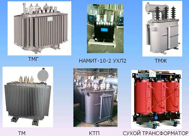
Types of Transformers
The rating of the current in the primary and secondary circuit determines the classification of transformers. In common types, the index is in the range of 1-5 A.
Separating unit does not provide for the connection of both spirals. The equipment provides galvanic isolation, i.e., the transmission of the pulse in a non-contact manner. Without it, the current flowing between the circuits is limited only by the resistance, which is not taken into account due to its small value.
The matching transformer provides the matching of different resistance values to minimize the distortion of the pulse shape at the output. It serves to organize galvanic isolation.
Before finding out what are the power direction transformers, it is noted that they are produced to work with high-power networks. Alternating current devices change the energy values in receiving installations and work in places with a large capacity and rate of change of electricity.
A rotary transformer should not be confused with a rotating equipment, a machine for converting the angle of rotation into circuit voltage, where the efficiency depends on the speed of rotation. The device transmits an electrical impulse to moving parts of the machinery, such as the head of a VCR. Dual core with separate windings, one of which rotates around the other.
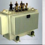
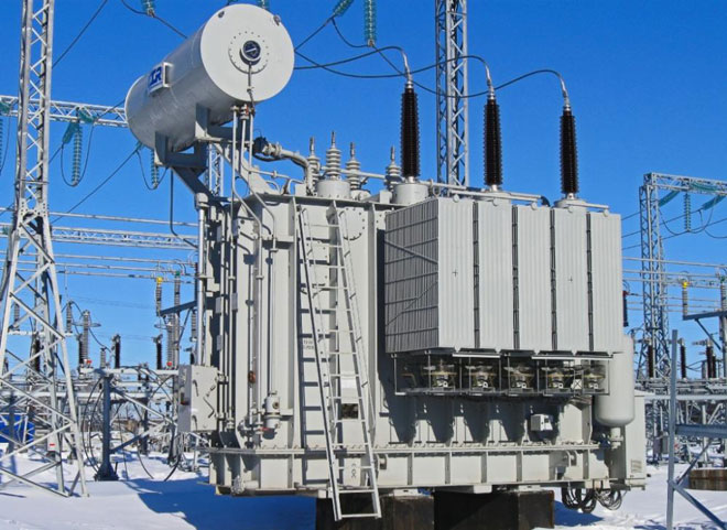
The oil-filled unit uses coil cooling with special transformer oil. They have a closed-type magnetic circuit. In contrast to airborne types, they can interact with high-power networks.
Welding transformers to optimize the operation of equipment, lower the voltage and create high frequency current. This is due to changes in inductive impedance or no-load characteristics. Step regulation is performed by the layout of the electrical winding on the conductors.